|
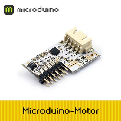
Microduino-Motor is a motor driver control module with the PWM control function. It can use to control Dual bridge type low voltage step motor, one or two DC motor.
Widely used in stmart car control and robot.
Feature
- Internal PWM current limit control
- Synchronous rectifier and reduce power consumption
- Under-voltage lockout
- Low RDS(on)output
- Dc motor braking mode
- Sleep function
- Cross current protection
- Thermal Shutdown
- size small
Specification
- 20 pins
- 4 mm×4mm×0.75mm size
- QFN package and with an enhance the bonding pad exposed to heat
- 100% Matte tin plated pin
Electrical specifications
- VCC voltage:5V
- VMOT voltage:2.5~9V
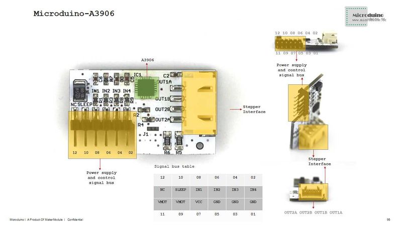
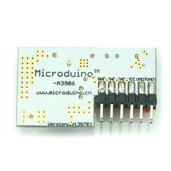
Pin Description
| Microduino Motor Pin |
Microduino Pin |
Function
|
| SLEEP |
Microduino IO port |
Sleep logic input, low active
|
| IN1 |
Microduino IO port |
Control input
|
| IN2 |
Microduino IO port |
Control input
|
| IN3 |
Microduino IO port |
Control input
|
| IN4 |
Microduino IO port |
Control input
|
| VMOT |
Connect external power |
external power to motor
|
| VCC |
VCC |
power to A3906 and Microduino
|
| GND |
GND |
Common GND
|
Document
Driver chip:A3906 File:A3906-Datasheet.pdf
Development
DC motor connection
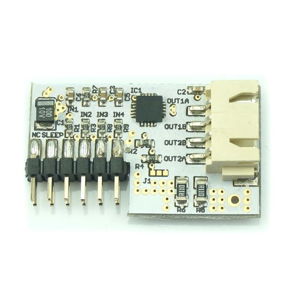
Connect one DC motor to OUT1A,OUT1B, the other DC motor connect to OUT2A,OUT2B.
DC motor control mode
| IN1 |
IN2 |
IN3 |
IN4 |
OUT1A |
OUT1B |
OUT2A |
OUT2B |
Function
|
| 0 |
0 |
0 |
0 |
Off |
Off |
Off |
Off |
Close
|
| 1 |
0 |
1 |
0 |
High |
Low |
High |
Low |
Forward
|
| 0 |
1 |
0 |
1 |
Low |
High |
Low |
High |
Backward
|
| 1 |
1 |
1 |
1 |
Low |
Low |
Low |
Low |
Stop
|
Step motor connection
- Connect step motor to Microduino Motor module:
- Four wire two phase stepper motor has two sets of coil A and B. Each group of coil resistance is very small, only a few ohm.
A and B group is absolute insulation, disconnected. Measured with a multimeter, conducted wire is one set.
- Identified the A and B group, connect one group to OUT1A, OUT1B, another group connects to OUT2A, OUT2B.
Step motor control mode
| IN1 |
IN2 |
IN3 |
IN4 |
OUT1A |
OUT1B |
OUT2A |
OUT2B |
Function |
|
| 0 |
0 |
0 |
0 |
Off |
Off |
Off |
Off |
Disabled |
Disabled
|
| 1 |
0 |
1 |
0 |
High |
Low |
High |
Low |
Full Step 1 |
1/2 Step 1
|
| 0 |
0 |
1 |
0 |
Off |
Off |
High |
Low |
|
1/2 Step 2
|
| 0 |
1 |
1 |
0 |
Low |
High |
High |
Low |
Full Step 2 |
1/2 Step 3
|
| 0 |
1 |
0 |
0 |
Low |
High |
Off |
Off |
|
1/2 Step 4
|
| 0 |
1 |
0 |
1 |
Low |
High |
Low |
High |
Full Step 3 |
1/2 Step 5
|
| 0 |
0 |
0 |
1 |
Off |
Off |
Low |
High |
|
1/2 Step 6
|
| 1 |
0 |
0 |
1 |
High |
Low |
Low |
High |
Full Step 4 |
1/2 Step 7
|
| 1 |
0 |
0 |
0 |
High |
Low |
Off |
Off |
|
1/2 Step 8
|
Application
Program download
Test program:File:Program Test A3906.zip
A3906 contorl two DB motors
- Use Microduino core and Microduino A3906's control function;
- Prepared hardware: Microduino FT232R、Microduino Core, Microduino Motor, two DC motors, 2.5~9V power;
- Prepared software: Microduino provides test program(Arduino part), Arduino IDE(1.0 release or upper);
- Start Arduino IED,open the Microduino test program, board type choose "Microduino Core (Atmega328P@16M,5V)", download directly;
Microduino core and Microduino Motor connected Pegboard:
- Set up the circuit on pegboard as following picture: (blue line at the bottom)
- Microduino Motor drive DC motor test:
- Connect 5V or 9V power, motor can't rotate at the intial state:
- Start Arduino IED serial monitor
- Input 0000, enter, two motors don't rotate
- Input 0101, enter, Two motors forward
- Input 0110, enter, one motor forward, another backward
- Input 1001, enter, one motor backward, another forward
- Input 1010, enter, two motors backward
- Input 1111, enter, two motors stop
Bug
History
Pictures
Video
|


