Overview
Project Background
- Joypad may be born to be the controller of the aircrafts.
- It can remotely control the Cube Robot, Self-balance Robtor and the Quadcopter.
- By stacking different Microduino modules, you can achieve multiple ways of communication.
- You can also set the functions through TFT colored screen.
- Get your Joypad started and play your Robot car and the Quadcopter.
Bill of Material
| Components |
Number |
Function
|
| Joypad mainboard |
1 |
Motherboard
|
| Core module |
1 |
Core
|
| Communication module |
1 |
Communication
|
| TFT Screen |
1 |
Display
|
- Joypad offers several modules for option.
- So, you can refer to the following function/compatibility list to choose the right core module, communication module and the function module.
- Joypad is compatible with any one of Microduino core modules except for Microduino-CoreUSB.
| 【Function】Module/【Function】Core
|
【Not support communication】 Core
|
【Not support communication】 Core+
|
【Communication/Quadrotor】 CoreRF
|
| 【Communication /Robot】 nRF |
YES |
YES |
YES
|
| 【Communication /Quadrotor】 BLE |
YES |
YES |
NO
|
| 【Somatosensory】 Motion |
NO |
YES |
YES
|
Module Selection
- Applied in: Remote control of the Robot
- Adopt Microduino-Core as the core module
- Adopt nRF24 as the communication module.
- Applied in: Remote control of the Quadrotor
- Adopt Microduino-CoreRF as the core module.
- The CoreRF comes with 2.4G communication function and need no other core to work with.
- Applied in : Motion control of the Quadrotor
- Adopt CoreRF as the core module.
- The CoreRF comes with 2.4G communication function and need no other core to work with.
- Adopt the Motion as the somatosensory module.
- Applied in :Motion control of the Robot
- Adopt Microduino-Core+ as the core module.
- nRF24 as the communication module.
- Motion as the somatosensory module.
Bill of Material
| Component |
Number |
Function
|
| Joypad mainboard |
1 |
Mainboard
|
| Nylon screw |
8 |
Fixation
|
| Nylon nut |
8 |
Fixation
|
| Nylon column |
8 |
Fixation
|
| White key cover |
4 |
Key
|
| Joystick |
2 |
Rocker
|
| 1.27mm 8P cable |
1 |
Connect TFT screen
|
| 10440 3.7V Li-ion battery(for option) |
1 |
Power supply
|
| Micro-USB cable(for option) |
1 |
Program download
|
Step-1:Programming
Source Code Download
Download the program from the address below:
[Joypad_RC]
Stacking Modules
- Connect Microduino-USBTTL with a USB cable, stack it with your core module for program uploading.
- Note: Please upload programs before stacking all modules.
Configuring the Environment
- Open Arduino IDE for Microduino environment. (For buildup reference: AVR Core:Getting started)
- Make sure choose the right "Board" and "Processor", select the corresponding port number (COMX).
Program Download
- Open " Joypad_RC.ino " in the programs you've downloaded.
- Click"→" and download programs to the development board.
Step-2: Reference Voltage
- For matching input devices with any voltage on the Core and the Joypad: The reference voltage of the Joystick and switch is adjustable.
- If you choose CoreRF or other core modules in 3.3V like Core, Core+.
- Then you'll need to re-set the reference voltage of the Joypad's mainboard via the jumper wires.
Step-3:Power-on via battery
Battery Specification Supportable
| Function/battery type
|
10440 Li-ion battery(3.7V)
|
AAA battery(1.5V)
|
| If it supports one battery |
YES |
NO
|
| If it supports two batteries |
YES |
YES
|
| If it is rechargeable |
YES |
NO
|
- Here we suggest using 10440 Li-ion battery (3.7V)
Activate the Power Management Circuit
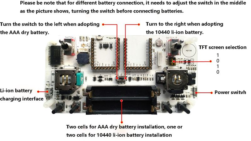
- For the battery usage, please refer to the picture below, toggle the switch (in the battery mode) to the right position and then connect into battery.
- After the connection, please make sure you plugged in the USB cable to "activate" the power management circuit of the Joypad.
- Then, you can control the power switch of the Joypad normally.
Power Quantity Reminder and Charging(only for 10440 Li-ion battery)
- When you are using two AAA batteries, please don't adopt USB cable for power supply or it'll cause battery burning.
- When the "LOW" indicator near the USB cable goes on, it means the battery power is insufficient.
- When using the AAA batteries, the indicator will be always on due to low voltage.
- Plug in the USB cable and you can start charging.
- The charging indicator will go on, and then will turn weak or go out when finishing charging.
Step-4: Buildup
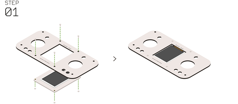
- Step 1:
- Insert the Microduino-TFT into the panel of the Microduino-Joypad.
- Fixate them withnylon screws and nylon nuts , make sure the Microduino-TFT installation is right.
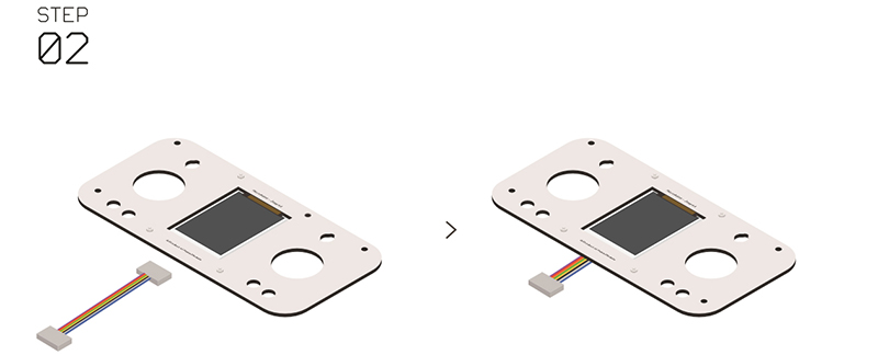
- Step 2:
- Insert the cable in the Microduino-TFT.
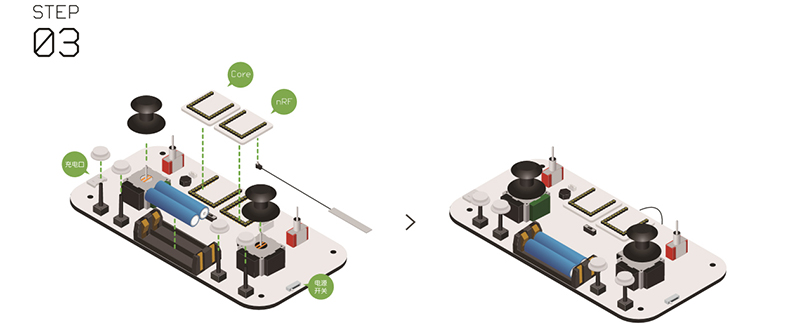
- Step 3:
- Install the communication module and the core module into the UPIN27 interface of the Joypad's baseboard.
- Make sure the "battery", "two rocker covers " and "four white keys " installed correct.
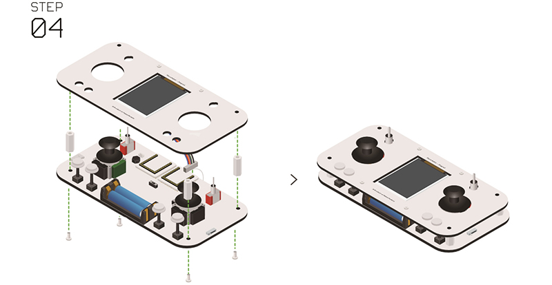
- Step 4:
- Connect the other side of the Microduino-TFT cable to the corresponding interface the baseboard.
- Install the nylon columns.
- Fixate the columns with nylon screws.
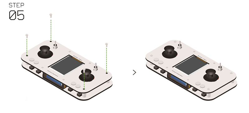
- Step 5:
- Fixate the four corners of the panel.
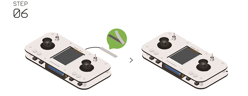
- Step 6:
- After the installation of the antenna, congratulations! you just completed the hardware buildup of the Joypad.
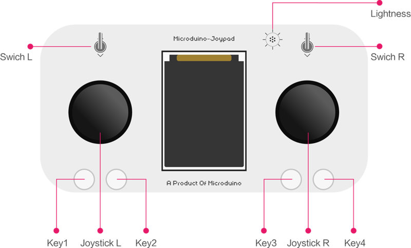
Step-5: Key Description
- Two rockers: Joystick L、Joystick R
- Two switches: Switch L、Switch R
- Four keys: Key1, Key2, Key3, Key4
- One Light sensor:
Step-6: Channel/Operation Description
- Joystick L controls YAW[3-channel] and THROT[channe-4l]; Joystick R controls ROLL[channel-1] and PITCH[channel-2].
- Key1, Key2, Key3 and Key4 respectively correspond to AUX1[channel-5], AUX2[channel-6], AUX3[channel-7] and AUX4[channel-8].
- "Switch L" targets at locking the throttle.
- "Switch R" starts small rudder mode and under this mode, the quantity of the rudder is becoming smaller.
Enter Configuration Mode
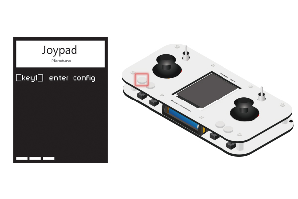
- After opening the Joypad for around 4s, please press down the Key1 and enter the configuration mode.
- Note: Please make sure entering the configuration mode 2s ahead of entering the operation interface. If not, please try to enter again.
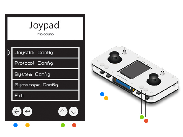
- Find Key1-Key4 from left to right by checking the colors in the picture below.
- Press Key3 and Key4 to move the icon. Key1 means "Return" and Key2 refers to "Confirm".
Joystick Configuration
Calibration of the Joystick
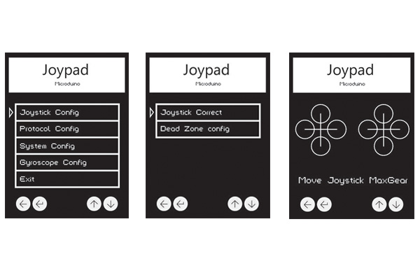
- Select "Joystick Config-Joystick Correct" and enter the calibration mode of the Joystick.
- After that, you'll see two crosses at the beginning.
- Move the left and the right rockers around to the upmost.
- And you'll see cycles around the crosses. When the cycle gets to its largest, it indicates the rocker has been turned to the upmost.
"Dead zone" setting for the Joystick
- Choose " Joystick Config-Dead Zone config " and you can set the "dead zone".
- The bigger of the value you set, the more insensitive the Joystick gets.
Communication Protocol Configuration
Communication Mode
- Select " Protocol Config-mode " and enter the setting.
- "Quadro" indicates Quadrobot mode and "nRF24" incates nRF mode.
Channel Configuration of the Quadro Mode
- Select " Protocol Config-Quadrotor Channel " and enter the setting.
Channel Configuration of nRF Mode
- Select " Protocol Config-nRF24 Channel " and enter the setting.
System Configuration
Them Configuration of the Display Screen
- Select " System Config-TFT Theme " and enter the setting.
Display Screen Spinning Configuration
- Select " System Config-TFT Rotation " and enter the setting.
MCU Reference Voltage Configuration
- Select " System Config-MCU Voltag " and enter the setting.
Motion Configuration
- Select " Cyroscope Config " and enter the setting.
Exit Configuration Mode
- Select " Exit " and enter the setting.
FAQ
- Q: Does Joypad support AAA batteries?
- A: Yes, it'll need two. But we don't recommend that.
- Q: Why don't you recommend AAA batteries?
- A: The battery protection and low power indicator of the Joypad are designed for the 3.7V Li-ion battery. Two cells of AAA batteries may trigger circuit protection and cause the illusion of no electricity,
- Q: What battery does Joypad recommend?
- A: Single or two cells of 10440 3.7V Li-ion batteries.
- Q: What core module does we need to control the Quadrobot?
- A: CoreRF, which comes with communication function and therefore, it needs no other communication modules.
|
