Difference between revisions of "Lesson 9--Microduino used as 0-5V range voltmeter (simulate a multimeter)"
(Created page with "{| style="width: 800px;" |- | ==Objective== We have learned how to use read analog port, then mapping to 0~1024. Today we will make a 0-5v voltmeter by Microduino's analog por...") |
(→Objective) |
||
| (4 intermediate revisions by 3 users not shown) | |||
| Line 1: | Line 1: | ||
| + | {{Language|第九课--Microduino_做0-5V量程的电压表(万用表的使用)}} | ||
{| style="width: 800px;" | {| style="width: 800px;" | ||
|- | |- | ||
| | | | ||
==Objective== | ==Objective== | ||
| − | We have | + | We have introduced the reading (0-1024) of the analog port before. Now, we will use the analog port of microduino to make a voltmeter with the range of 0-5 V. |
| + | |||
| + | '''Notice: The circuit design of the experiment has no relatively complicated protection circuit. So please don't use more than two AA batteries and don't use the circuit to measure the lithium battery or other power supply!!''' | ||
| − | |||
==Equipment== | ==Equipment== | ||
*'''[[Microduino-Core]]''' | *'''[[Microduino-Core]]''' | ||
| Line 12: | Line 14: | ||
**Breadboard Jumper one box | **Breadboard Jumper one box | ||
**Breadboard one piece | **Breadboard one piece | ||
| − | **1kΩ resistor | + | **1kΩ resistor one |
**USB Data cable one | **USB Data cable one | ||
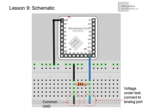
==Experimental schematic== | ==Experimental schematic== | ||
| − | [[File: | + | [[File:less0n9-schematic.jpg|center|600px|thumb]] |
The purpose of using 1K resistor is that in the case of measuring end vacant, the GND reference guide to measure port, and avoid vacant interfaces interference. | The purpose of using 1K resistor is that in the case of measuring end vacant, the GND reference guide to measure port, and avoid vacant interfaces interference. | ||
| Line 50: | Line 52: | ||
==Result== | ==Result== | ||
| − | + | When the measured voltage changed, refrest the date every 1s. If there is a gap between two voltage value, this is normal. | |
Because this is a low accuracy test. If you need a higt accuracy test, plesae refer to: | Because this is a low accuracy test. If you need a higt accuracy test, plesae refer to: | ||
http://www.hacktronics.com/Tutorials/arduino-current-sensor.html | http://www.hacktronics.com/Tutorials/arduino-current-sensor.html | ||
==Video== | ==Video== | ||
|} | |} | ||
Latest revision as of 10:40, 5 May 2014
| Language: | English • 中文 |
|---|
ObjectiveWe have introduced the reading (0-1024) of the analog port before. Now, we will use the analog port of microduino to make a voltmeter with the range of 0-5 V. Notice: The circuit design of the experiment has no relatively complicated protection circuit. So please don't use more than two AA batteries and don't use the circuit to measure the lithium battery or other power supply!! Equipment
Experimental schematicThe purpose of using 1K resistor is that in the case of measuring end vacant, the GND reference guide to measure port, and avoid vacant interfaces interference. Programfloat temp; // Define a float variable temp to save data.
void setup()
{
Serial.begin(115200); //Set baud rate 9600
}
void loop()
{
int V1 = analogRead(A0);
// Read the voltage date form A0 and stores in V1, the voltage range is 0-5v and return value is 0-1024.
float vol = V1*(5.0 / 1023.0);
//Convert the V1 to actual voltage value and stores in vol
if (vol == temp)
//Use to filter duplicate data, Only the voltage value and the last isn't same then output the value.
{
temp = vol; //Compared, then store in temp variable "temp"
}
else
{
Serial.print(vol); //Serial output voltage, nowrap
Serial.println(" V"); //Serial output character "V", and wrap
temp = vol;
delay(1000); //Wait for 1s, use to refresh the data
}
}We don't use the function map() to the conversion, you can try it by yourself. ResultWhen the measured voltage changed, refrest the date every 1s. If there is a gap between two voltage value, this is normal. Because this is a low accuracy test. If you need a higt accuracy test, plesae refer to: http://www.hacktronics.com/Tutorials/arduino-current-sensor.html Video |
