|
|
| Line 81: |
Line 81: |
| | | | |
| | | | |
| − | | + | <br style="clear: left"/> |
| − | | |
| | '''The main components''' | | '''The main components''' |
| | | | |
| Line 91: |
Line 90: |
| | *Button switch: TS-018 [[Media:TS-018.pdf]] | | *Button switch: TS-018 [[Media:TS-018.pdf]] |
| | *Toggle switch: MSK-12C01 (1P2T) [[Media:MSK-12C01 (1P2T) pdf]]. | | *Toggle switch: MSK-12C01 (1P2T) [[Media:MSK-12C01 (1P2T) pdf]]. |
| − |
| |
| − |
| |
| − |
| |
| − | <br style="clear: left"/>
| |
| − |
| |
| | | | |
| | | | |
|
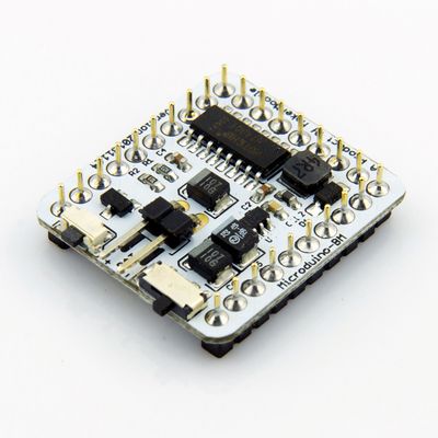
Microduino-BM module is an integrated single-cell Li-ion battery charge management,
power detection and LED indication, the boost to 5V output, LDO to 3.3V output of discharge management module.
|
Features
- Charge and discharge management, power detection, 5v boost, 3.3v LDO highly integrated;
- DIP switch gear charging and discharging, a key to open, hibernation module;
- Small, cheap, stack, open;
- Unified Microduino interface specification, and rich peripheral modules can be easily and flexibly with other eligible Microduino interface specification modules, sensors for quick connection and expansion;
- 2.54 pitch row female connector for easy integration into breadboard.
|
Specifications
- First, let's look at the interface of the module:
- A key switch
- A two tranches DIP switch gear
- One pair of 2.54 battery interface ("+" then the battery positive, "-" then the battery negative)
- UPIN27 on the role of interface has 5V, 3V3, GND:
|
Charging
- First access external 5V charging power supply, and then switch to "IN", the module into the charging state, then four LED lights do Surge charging indication (detailed display mode, please refer to HT4901 documentation), the maximum charging current to 500mA, charging is completed * after the first switch to OUT, and then unplug the external 5V charging power.
- Note:
- Always follow the charging process: make sure switch to OUT, plug in the battery, charging access external 5V power supply, the switch in the IN, start charging, charging is completed, the switch to OUT, unplug the external 5V Charge power.
- Recommended charging power supply: Voltage 5v, current 600ma above;
- Not add pressure drop impact elements (diodes) in the charging circuit, so as not to reach the charging voltage, thereby affecting the charging current.
|
Discharge
- Make sure the switch is in the OUT, after access to the battery, in the standby mode, short press button switch (time> 50mS), the module that wakes up from standby mode; boost output started at this time, while open UPIN27 the GND circuit: Interface 5V 5V output voltage, maximum current of 500mA; while 3V3 interface output voltage of 3.3V, the maximum current 250mA.
- When the battery voltage under-voltage (3.3V) or enter limiting / boost output short circuit protection, enter standby mode.
- Note:
- Make sure the switch is in the OUT and then start boost output;
- please do not toggle switch in Battery-powered process.
|
Power detection
- Make sure the switch is in the OUT, after access to the battery, press button switch on the built-in battery detection; and through the four LED indicator for battery indicator, battery indicator after 3 ~ 5S closed.
|
Standby
- (Standby circuit is disconnected UPIN27 the GND and BM can be controlled within the overall power consumption of 30uA)
- Make sure the switch is in the OUT, if any action after accessing the battery, then the default is in standby mode.
- When you've turned on discharge mode by pressing the button switch (3s above) to enter standby mode.
- Intelligent Detection: No charge input, no discharge output (<10mA) within three minutes into standby mode.
|
Documents
- Snapshot of Microduino-BM schematic
- Microduino-BM Eagle source file 【download】
- Microduino-BM main chips and devices
The main components
|
Development
|
Applications
|
Pictures
|
History
|


