Difference between revisions of "Microduino-Module Amplifier"

From Microduino Wiki
Jump to: navigation, search
(Development)
Line 34: Line 34:
  
 
==Development==
 
==Development==
*Make sure the 5V power supply current can reach 500ma and the FT232R debugging is not recommended since FT232R's output current is small.
+
*Make sure the current(5v) can reach 500ma. The FT232R debugging is not recommended since FT232R's output current is small.
  
 
===Arduino library and supported package===
 
===Arduino library and supported package===
Line 40: Line 40:
  
 
===How to use the library===
 
===How to use the library===
*The CS pin of Microduino-SD module is D4 in the original library, needed to be changed to D7;
+
*The CS pin of Microduino-SD module needs to be changed from D4 in the original library to D7;
*Since the original library can not directly support Microduino Core +, we have modified this library to solve this problem;
+
*Since the original library can not support Microduino Core+ directly, we have modified this library to solve this problem;
  
*TF card(2GB of memory and lower) in FAT format is recommended.
+
*TF card(2GB of memory and lower) in FAT format is recommended.
  
  
===Externally controlled low-power shutdown===
+
===Low-power shutdown of external control===
 
*In many applications, the shutdown port's level conversion is finished by the controller, but it can also be achieved by a one-way blade switch;
 
*In many applications, the shutdown port's level conversion is finished by the controller, but it can also be achieved by a one-way blade switch;
 
**Connect a pull-up resistor on the third pin of the second row pin female near the D13 pin, then disconnect the switch. This pin will be pulled low, so the Amplifier begin to work;
 
**Connect a pull-up resistor on the third pin of the second row pin female near the D13 pin, then disconnect the switch. This pin will be pulled low, so the Amplifier begin to work;
**Turn on the switch,pthe ull-up resistor will pull up the voltage,making Microduino-LM4863 stop work.
+
**Turn on the switch,the pull-up resistor will pull up the voltage,making Microduino-LM4863 stop working.
  
 
==Application==
 
==Application==

Revision as of 09:45, 30 July 2014

Language: English  • 中文
Microduino-LM4863

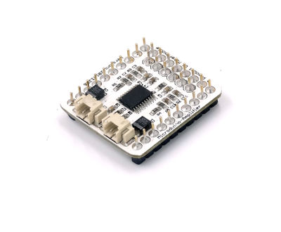
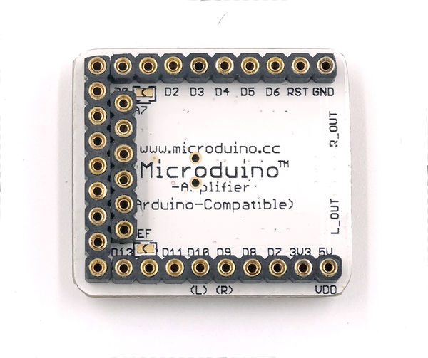
Microduino-Amplifier is the double-channel audio power amplifier module.

Feature

  • 2.54 connector with good compatibility;
  • Power-on noise offset and uni-gain stable;
  • Small, cheap, stackable and open
  • Open hardware circuit design and Arduino compatible programming development environment;
  • Uniformed Microduino interface standard and rich peripheral modules, capable of having a fast and flexible connection and extension with other modules and sensors in accord with Microduino interface standard;
  • Easy to be integrated to pegboards with a 2.45-pitch female header connector interface.


Specifications

  • Offer 2.2W output for 4Ω load;
  • Operating Voltage:2.0-5.5V;
  • Externally controlled low-power shutdown mode with the typical shutdown current of 0.7uA.
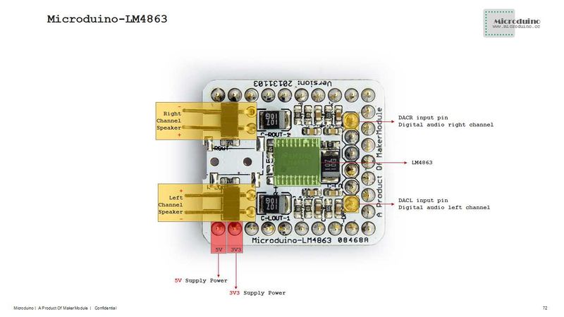
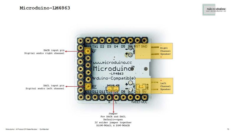
Microduino-LM4863-Pinout

Document

Eagle PCB File:Microduino-LM4863.zip

Main Component

Development

  • Make sure the current(5v) can reach 500ma. The FT232R debugging is not recommended since FT232R's output current is small.

Arduino library and supported package

How to use the library

  • The CS pin of Microduino-SD module needs to be changed from D4 in the original library to D7;
  • Since the original library can not support Microduino Core+ directly, we have modified this library to solve this problem;
  • TF card(2GB of memory and lower) in FAT format is recommended.


Low-power shutdown of external control

  • In many applications, the shutdown port's level conversion is finished by the controller, but it can also be achieved by a one-way blade switch;
    • Connect a pull-up resistor on the third pin of the second row pin female near the D13 pin, then disconnect the switch. This pin will be pulled low, so the Amplifier begin to work;
    • Turn on the switch,the pull-up resistor will pull up the voltage,making Microduino-LM4863 stop working.

Application

Program Download

The Audio experiment using Core and SD

  • Hardware:Microduino FT232R、Microduino Core、Microduino SD、Microduino LM4863;
  • Software:Arduino IDE(1.0 release upper)、Microduino provides test program(Arduino part)、SimpleSDAudio library、Audio file creation tools;
  • Put the downloaded library to the libraries folder of Arduino IDE installation;
  • Copy the "EXAMPLE.AFAM" in "examples" folder to memory card;
  • Start Arduino IDE,open the "BareMinimum" program, choose "Microduino Core (Atmega328P@16M,5V)"and download directly;
  • Then you can listen it!
    • If you want to play your own audio, just need to change the "EXAMPLE.AFM" to the name of the generated audio file.

The process of making an audio file

  • Convert any audio file into a. Wav format using a software "Format Factory";
  • Generate an audio file:
    • We need to use a SoX-based tool, and then choose the appropriate conversion process according to the operating frequency of the modules;
    • Decompress the tool,then enter“Arduino with 16 MHz”folder,put the audio file into this folder,and drag to "FullRate@16MHz_Stereo.bat" (16M full stereo) batch on;
    • then you can convert the file. A dialog box will pop up "Press any key to continue ...";
    • After that, you will find a new folder and the converted file is there.

Pictures

Microduino LM4863 Front


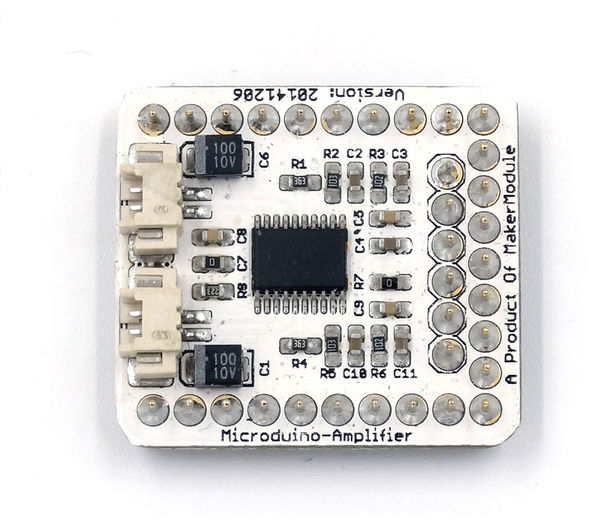
Microduino LM4863 Back