|
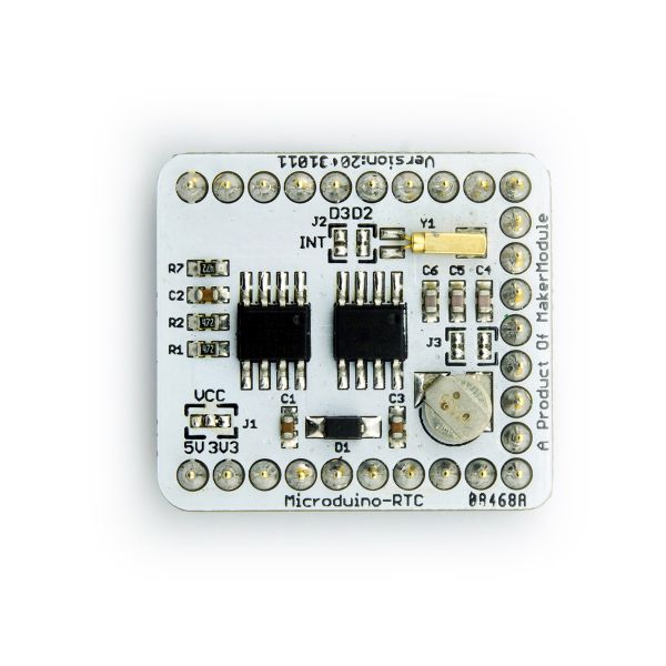
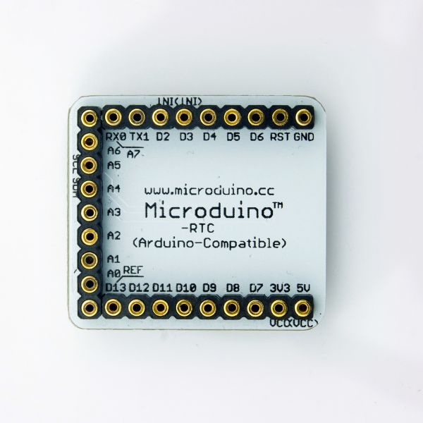
Microduino-RTC Module is a Real Time Clock module based on NXP CMOS PCF8563. RTC module uses TWI/I2C interface for communication. Data can be backed up with the addtional AT24c32 EEPROM. With an onboard capacitor, RTC module keeps time for serveral minutes after power disconnected. PCF8563 uses external crystal, and can provide timer intterupt tigger.
- Microduino RTC Real Time Clock Module
- PCF8563 CMOS Real-Time Clock (RTC)
- Two Wire Interface (I2C)
- Backup by additional EEPROM AT24C32
|
Feature
- Based on PCF8563 clock chip with century mark, seconds, minutes, hours, day, week, month, year;
- Use the I2C interface to communicate with the Core/Core+ module;
- Use EEPROM AT24C32 with I2C interface;
- Low-power clock chip, the typical current value 0.25μA, plus a super capacitor, the clock is still running after a power diconnect;
- Open source hardware circuit design, compatible with the Arduino IDE development environment for programming;
- Define unified interface Microduino specification and contain rich peripheral modules. Set up the quick connection with other Microduino modules and sensors easily and flexibly.
- 2.54 pitch row female connector for easy integration into breadboard.
|
Specification
- Clock chip: PCF8563;
- Low-power CMOS real-time clock/calendar chip;
- Provides a programmable clock output, an interrupt output and a brown-out detector, transfers all address and data via the I2C serial bus interface;
- The maximum bus speed is 400Kbits/s, after read and write data, the embedded word address register is automatically generated increment.
- EEPROM chip:AT24C32
- Provide 32,768 serial electrically EPROM, organized as 4096 words × 8-bit length;。
- Cascade feature allows AT24C32 articulated eight devices on the same I2C bug, the replication cycle of millions lives and saved the data to 100 years with a write-protect function.
- Super capacitor:XH414
- Provide a power-down timing function in a time slot。
文档
Eagle PCB Download
主要元件
主要元器件
开发
Arduino库及支持包
应用
程序下载
- 所需要准备的硬件有:Microduino FT232R、Microduino Core、Microduino RTC、Microduino OLED;
- 所需要准备的软件有:Microduino提供的测试程序(Arduino端)、Arduino IDE(1.0版本以上)、Rtc_Pcf8563库;
- 将下载好的库文件夹放入Arduino IDE安装文件夹内的libraries中;
- 启动Arduino IED,打开Microduino提供的测试程序,板卡选择Microduino Core (Atmega328P@16M,5V),直接下载即可;
测试掉电续时:[RTC_Time]
- 开机显示载入过程,包括:Welcome!Load Time...,Microduino图标。每隔1s左右载入一个项目,载入完毕进入主程序界面;
- 第一行显示的日期,日期格式:xx/xx/xx(年/月/日)
- 第二行显示的时间,包括星期。时间格式:xx:xx:xx(时:分:秒),接着后面显示星期(英文,不含缩写);
- 第三行固定显示:Microduino-RTC v1.0 201310,因为字符较多,采用小字体;
- 程序运行后,切断电源,等一段时间后上电观察到第二行显示的时间是掉电后继续运行的时间,而不是初始化设置得时间,也是掉电前1s显示的时间;
- (注意:RTC是可编程时钟输出,通过vosettime()函数来设置时间,下载完毕后注释掉vosettime()函数再下一次才能掉电继续计时,不然上电重启之后又恢复设置得值)
测试EEPROM读写:[RTC_EEPROM]
- 开机显示载入过程,包括:Welcome!,Load EEPROM,Microduino图标。每隔1s左右载入一个项目,载入完毕进入主程序界面;
- 第一行显示随机函数值,第一个数据是10到99的随机数(Random);第二个数据是EEPROM掉电后上电读取的数值;
- 第二行固定显示:Microduino-RTC v1.0 201310,因为字符较多,采用小字体;
- 在测试过程中可拔掉电源后插上电源,就可以看到掉电前随机数变换的最后一个值更新到了读取EEPROM显示值处。
测试定时中断:[RTC_Alarm]
- 开机显示载入过程,包括:Welcome!,Load Time...,Load Alarm..,Microduino图标。每隔1s左右载入一个项目,载入完毕进入主程序界面;
- 第一行显示的时间。时间格式:xx:xx:xx(时:分:秒);
- 第二行固定显示:Microduino-RTC v1.0 201310,因为字符较多,采用小字体。
- 定时中断,当时间到达设定时间时,led每秒闪烁一次,持续1分钟,并且在OLED屏幕上看到倒计时时间。
|
Buy
|
History
- first version: 2013/July/06 passed internal testing
|
Pictures
|


