Difference between revisions of "Microduino NRF Wireless Gateway based on Enc Gateway -304 KIT"
(→Debugging) |
|||
| (4 intermediate revisions by 2 users not shown) | |||
| Line 4: | Line 4: | ||
| | | | ||
==Outline== | ==Outline== | ||
| − | + | Project: Microduino-NRF Wireless Communication Based on Microduino-Enc Gateway | |
| − | + | Objective: To set up a network with Microduino-Enc, PC and router,using Microduino-NRF to control the LED in the LAN. | |
| − | + | Difficulty: Elementary | |
| − | Time- | + | Time-consuming: Two-hour |
| − | + | Maker: Microduino Studio-YLB | |
|- | |- | ||
| Line 18: | Line 18: | ||
==Bill of Materials== | ==Bill of Materials== | ||
| − | *Microduino | + | *Microduino equipment: |
{|class="wikitable" | {|class="wikitable" | ||
|- | |- | ||
| Line 35: | Line 35: | ||
|Microduino Duo-V||1||For ease of building the circuit and debugging | |Microduino Duo-V||1||For ease of building the circuit and debugging | ||
|} | |} | ||
| − | *Other | + | *Other equipment: |
{|class="wikitable" | {|class="wikitable" | ||
|- | |- | ||
| Line 55: | Line 55: | ||
| | | | ||
==Debugging== | ==Debugging== | ||
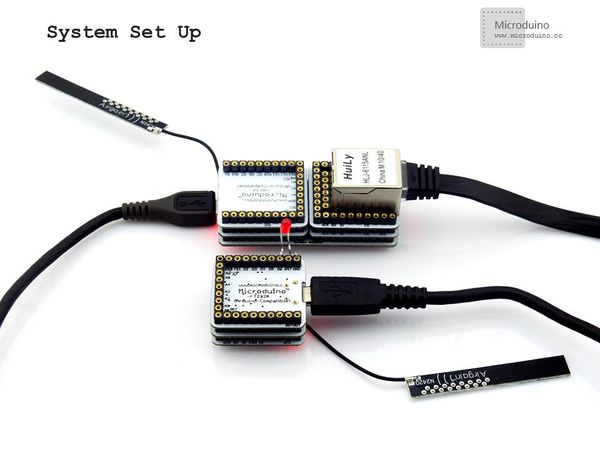
| − | Step | + | Step 1: Build the hardware |
| − | Master machine | + | Master machine control: |
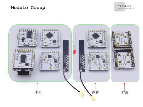
| − | + | Equipment: Microduino-Core+, Microduino Duo-V, Microduino-Enc, Microduino-nRF24, Router and network cables. | |
| − | Slave machine | + | Slave machine control: |
| − | + | Equipment: Microduino-Core, Microduino-nRF24 and Microduino-FT232R | |
|- | |- | ||
| | | | ||
| Line 69: | Line 69: | ||
|- | |- | ||
| | | | ||
| − | Step 2: | + | Step 2: Router network |
| − | Power router and connect the PC to network. | + | Power the router and connect the PC to network. |
Step 3: Download the program | Step 3: Download the program | ||
| Line 85: | Line 85: | ||
==Result== | ==Result== | ||
| − | After download | + | After finishing the download and getting the Microduino core networked, you can just open the gateway, click the ImageButton on the control interface to control the LED. Every time you click the button, the LED will have a status transmission, by which wireless network control can be achieved. Since it is a node-control, only the node set by the slave machine program can be controlled by the corresponding node of the gateway control interface. |
| + | |||
|- | |- | ||
| | | | ||
| + | |||
==Note== | ==Note== | ||
*Microduino Enc must be used with Microduino RJ45 together. | *Microduino Enc must be used with Microduino RJ45 together. | ||
| − | * | + | *Networking the devices needs to configure MAC and IP address of the Ethernet interface in the LAN. |
| − | *The gateway | + | *The node of the gateway and the slave machine should be matched. |
==Video== | ==Video== | ||
| − | + | ||
|} | |} | ||
Latest revision as of 05:40, 30 September 2016
| Language: | English • 中文 |
|---|
OutlineProject: Microduino-NRF Wireless Communication Based on Microduino-Enc Gateway Objective: To set up a network with Microduino-Enc, PC and router,using Microduino-NRF to control the LED in the LAN. Difficulty: Elementary Time-consuming: Two-hour Maker: Microduino Studio-YLB | |||||||||||||||||||||||||||||
Bill of Materials
| |||||||||||||||||||||||||||||
Document | |||||||||||||||||||||||||||||
DebuggingStep 1: Build the hardware Master machine control: Equipment: Microduino-Core+, Microduino Duo-V, Microduino-Enc, Microduino-nRF24, Router and network cables. Slave machine control: Equipment: Microduino-Core, Microduino-nRF24 and Microduino-FT232R | |||||||||||||||||||||||||||||
|
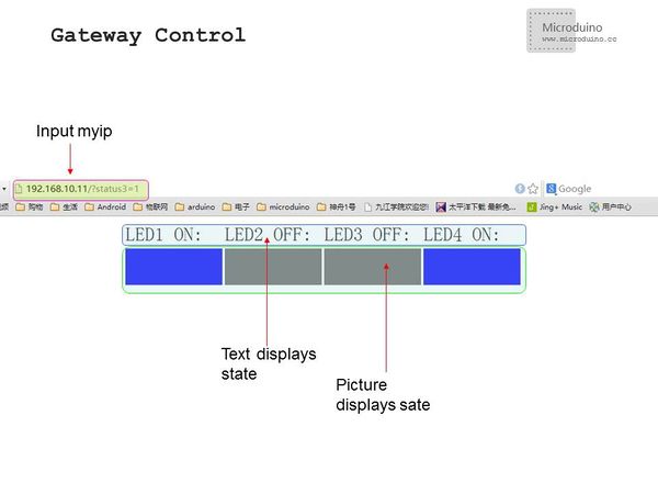
Step 2: Router network Power the router and connect the PC to network. Step 3: Download the program Start Arduino IED, open the Microduino example program and choose "Microduino Core +(Atmega644P@16M,5V)" as the board of the master machine and "Microduino Core (Atmega328P@16M,5V)" as the board of the slave machine, then download directly. Step 4: Control the LED in the LAN Open a new webpage, enter your IP address and you'll enter the control interface if you can connect the network successfully. | |||||||||||||||||||||||||||||
ResultAfter finishing the download and getting the Microduino core networked, you can just open the gateway, click the ImageButton on the control interface to control the LED. Every time you click the button, the LED will have a status transmission, by which wireless network control can be achieved. Since it is a node-control, only the node set by the slave machine program can be controlled by the corresponding node of the gateway control interface.
| |||||||||||||||||||||||||||||
Note
Video |


