|
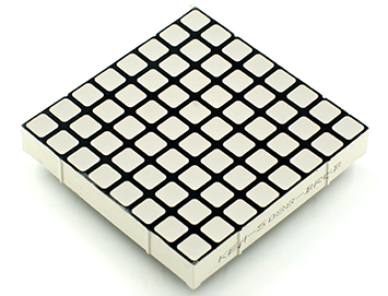
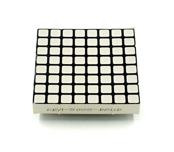
Sensor-Dot Matrix module is a 8x8 multi-color LED displaying matrix module, which can be used singly or multiply (combined into different shapes), which is used to display pictures or texts, or even simple animation.
Features
- 8x8 dot matrix, and the size is 60mm*60mm;
- The display quality of the color of each point is 15-bit, and the RGB tricolor 32-level adjustment, and integral 32k colour color display effect;
- Support IIC communication protocol, and the IIC address can be set(1~64). THe dot matrix sequence adopts plane rectangular coordinate system, whcih is easy to control;
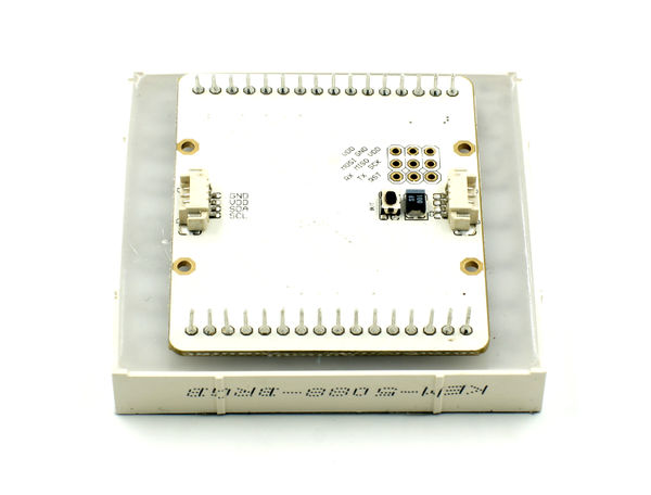
- With 2 IIC interfaces onboard, which makes the cascade between multiple dot matrixes easy;
- With one I/O port which can flexibly control the color of each lamp bead;
- Open-source hardware circuit design and Arduino-compatible programming development environment;
- With unified Microduino interface specification and abundant peripheral modules, which make it can be quickly extended and connected with other modules and sensors meeting the Microduino interface specification, conveniently and flexibly;
Specification
- Electrical specification
- Working voltage: 5V
- Working current: maximum 300mA
- IIC communication speed: 400Kbps
- Display quality
- Three primary colors gray: 32-level adjustable
- Size of single point: 6mm*6mm
- Control
- Set IIC address(1~64) through the buttons on the back of the module, and the method is as following.
Document
Eagle PCB:
Download: http://pan.baidu.com/s/1nuuTv8P
Main Component
Development
Set Method of the Address of Dot Matrix
- Check the address of the dot matrix:
- After the Sensor -Dot Matrix is powered on, during the initial 3s, it is in a state of IIC address initialization.
- At this time, the dot matrix will display green points of which the number represents the address value of the current dot matrix. If you haven’t pressed the setting button down during this 3s, the dot matrix will enter working state, and the IIC address of the dot matrix is that displayed. At this time, the display state of the dot matrix can be controlled by IIC.
- Enter dot matrix address setting state:
After the module Sensor-Dot Matrix is powered on, press the setting button down within the 3s of IIC address initialization, and the green points representing the address value will change into white, which says it has entered the address setting state.
- Change the address of the dot matrix:
- After enter the address setting state, press the button down, and the address will be changed. The range of the address is 1~64(the white representing the address value will change along with it).
- Pressing the button slowly(the interval between 2 times of pressing the button is greater than 0.5s) will add the address;
- Pressing the button quickly (the interval is less than 0.5s) will reduce the address.
- Exit the dot matrix setting state:
- After adjust the dot matrix to the required set value, long press the button, after 8s, the white points representing the address value will die out, and it exit the address setting state, entering working state. The IIC address at this time is the set address.
Arduino Library and Support Package
- Adopt adafruit_NeoPixel library file:
Application
Dot Matrix Library Specification
For the introduction of the code, please refer to点阵屏幕代码说明
Purchase
Gallery
|


