Difference between revisions of "Sensor-Pulse"

From Microduino Wiki
Jump to: navigation, search
(Specification)
(Document)
Line 45: Line 45:
  
 
==Document==
 
==Document==
*Chip: '''[[File: APDS-9008.pdf]]''' '''[[File: MCP6001.pdf]]'''
+
*Schematic diagram: '''[[File: Sensor-Pulse.Zip]]'''
*Schematic: '''[[File: Microduino_Pulse.Zip]]'''
+
*Main chip: '''[[File:SON1303_datasheet.pdf ]]'''
 
+
*Extension document: [https://forum.microduino.cn/topic/259/microduino%E5%BF%83%E8%B7%B3%E6%A8%A1%E5%9D%97%E4%B8%AD%E6%96%AD%E6%B3%95%E6%B5%8B%E9%87%8F%E4%B8%A4%E5%88%99%E7%AE%80%E4%BB%8B Pulse Module Interrupt Method Measurement]
  
 
==Development==
 
==Development==

Revision as of 08:04, 10 November 2016

Language: English  • 中文
Sensor-Pulse

The product number of Sensor-Pulse is: MSDI31

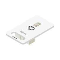
Sensor-Pulse is a heart rate or pulse sensor of photoelectrical principle.

Sensor-Pulse takes advantage of the sensitivity of the infrared with specified wavelength to the change of the blood volume produced by the blood microcirculation in the end of the blood vessel to detect the change of fingertip blood caused by heart beat.

The sensor can output the completed pulse wave voltage signal reflecting the change of the fingertip blood volume.


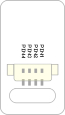
Introduction of Pins

Sensor backpin.png
  • Pins of the sensor:
    • PIN1: GND
    • PIN2: VCC
    • General signal pins:
      • PIN3(IO1): digital/analog signal
      • PIN4(IO2): NC(null)
    • Special signal pins:
      • If it is IIC: IO1/IO2 are respectively SDA/SCL.
      • If it is soft serial port: IO1/IO2 are respectively tx/rx.
  • Special to Sensor-Pulse sensor pins
    • PIN1: GND
    • PIN2: VCC
    • PIN3(IO1): Analog read
    • PIN4(IO2): NC


Microduino sensor can communicate with core module through the connection with Microduino-Module Sensor Hub.

Features

  • SON7015 sensor ultra-low consumption, and the power consumption is 0.2mA.
  • With small size which is easy to install.
  • Analog signal

Specification

  • Electrical specification
    • Input voltage: 3.3~5V, and 6V at most
    • Working current: 15uA
    • Working temperature: -20~85℃
    • Output voltage: high level 5V, low level 0V
  • Size
    • Size of the board: 23.5mm*13mm
    • 1.27mm-spacing 4Pin interface connected with sensorhub
    • The CAD drawing of the sensor: File:Sensor CAD.zip
  • Function description
    • After press the sensor tightly on the skin, the digital output will be 1 or 0 along with the change of the blood.
  • Connection
    • This sensor can be connected to the following interfaces of core: D2~D13

Document

Development

Preparation

Program

  • Test Program:

Microduino_Pulse_measurement

Hardware Buildup

  • All hardware needed(Except core module): Microduino-Cube-S1, Microduino-OLED, Microduino-Sensorhub and a USB cable as well as some connectors.
  • Stack all modules together, insert the pulse sensor into the A0 slot of Microduino-Sensorhub with the connector and connect Microduino-OLED with Microduino-Cube-S1 board's IIC interface via an OLED wire.
  • Open test program, choose the right board, compile and download.
  • After download, you can see OLED's interaction interface. The first line shows pulse rate and the second lines displays time and calculate the total heartbeats.
    • The pulse sensor starts counting when you press your finger tip onto it and it will calculate heartbeats after around 10 seconds.
    • Move your finger away and the system will clear automatically .

Application

Microduino-Pulse sensor can be applied in smart hand belt, detecting heartbeats during physical exercise so that you can adjust yourself.


Project

Purchase

History

Pictures

  • Front
Microduino-Cube-Station Front
  • Back
Microduino-Cube-Station Back