Difference between revisions of "Sensor-Relay"

From Microduino Wiki
Jump to: navigation, search
m (Fengfeng moved page Microduino-Relay to Sensor-Relay)
(Document)
Line 31: Line 31:
 
==Document==
 
==Document==
  
*Schematic: '''[[File: Microduino_Relay.Zip]]'''
+
*Schematic diagram: '''[[File: Microduino_Relay.Zip]]'''
  
 
==Development==
 
==Development==

Revision as of 10:28, 26 August 2016

Language: English  • 中文
Microduino-Relay

Microduino-Relay is a relay module. It can be used in isolation control.


Features

  • Used in isolation control of high voltage and high current signal.

Specification

  • Input 5V operation voltage for primary side;
  • Output 10A 250VAC/10A 30VDC for secondary side;
  • 1.27mm-pitch 4PIN interface;
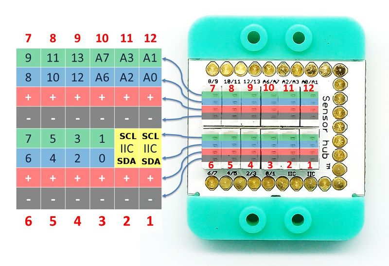
  • Pin description: GND, VCC, signal input and NC(empty). Since the input signal is simulated, it needs to be driven by digital interface(D0~D13), which can be connected the pins (3~10) of Sensorhub with the corresponding pins(D0,D2,D4,D6,D8,D10,D12).
MCookie-sensorhub rule.JPG

Document

Development

You can use Microduino-Relay to convert weak signal into high voltage, high current signal or for isolation control.

Application

  • All hardware needed: Microduino-CoreUSB, Microduino-USBTTL, Microduino-Sensorhub, dupont lines and USB cable.
  • Software:
  • Stack all modules and connect the Relay module to D2 port of Sensorhub with a wire.
  • Open Arduino IDE, select File→Examples→Digital→BlinkWithoutDelay program examples, choose the right board from Tools→Board and then compile.
  • Select the right port from Tools→Serial Port in Arduino IDE after compiling, then download program.
  • After download, you'll see STA light on the Relay module blinks one time each second. By measuring 2PIN crimping terminal on the Relay module with a multimeter, you can see that 2PIN crimping terminal also powers on and off each second.

Purchase

History

Pictures

  • Front
File:Microduino-Relay-F.JPG
Microduino-Relay Front
  • Back
File:Microduino-Relay -b.JPG
Microduino-Relay Back