The Use of Servo

From Microduino Wiki
Revision as of 01:11, 6 November 2015 by 1304410487@qq.com (talk)
Jump to: navigation, search

Overview

Unlike ordinary motor steering gear that will only turn around, servo can rotate according to your instructions to any 0-180 DEG or stop. So it is also called the servo motor, mainly constituted by shell, circuit board, non-core motor, gear and position detector.

Principle

It starts from the controller sending signal to the servo, getting through the circuit board chip to judge the direction of rotation, and then driving the non-core motor to rotate. The power is transmitted to the swing arm through the reduction gear while sending back signal by a position detector to judge whether it has already reached the location. The position detector is actually a variable resistance. When the servo rotates, the resistance values will be changed accordingly. By detecting the resistance values, you can know the angle of rotation.

Attention

The steering angle is within 0 -180 degrees. When the high level pulse is greater than 2.5ms, for a steering gear that has no self protection function, it'll usually cause the angle beyond the normal range. In that case, the internal DC motor will be in the stall state. In one or two minutes, it will cause the servo burning. When using it, please let it rotate among 45 degrees to 135 degrees as far as possible. Within the range, the steering angle is also more accurate.

Servo Connector

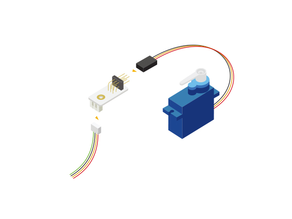
  • Standard servo motor has three control lines. Respectively for: power (VDD), (GND) and control signal lines, generally corresponding to the red line for power, gray line for the ground, orange line for the control signal line. The servo connector is noted with GND, VDD and 1/2. Please connect according to the corresponding relation.
  • A servo connector can be connected with two servos. In the hub, a base has two signal lines (GND, VCC, signal 0 and Signal 1). Corresponding to signal 0 is the steering gear on the connector above the gill (1 / 2). Signal 1 is the following gill (1 / 2).

Specification

Servo

  • Electrical specification
    • Operation voltage: 4.8-6V
  • Tech parameters
    • Torsion: 1.6kg-cm/4.8V &1.8kg-cm/6.0V
    • Speed:0.11sec/60°4.8V & 0.10sec/60° 6.0V
  • Size
    • Board size: 22.4mm*12.5mm*22.8mm
  • Interface
    • Power(VCC), ground(GND), signal(in)

Servo Connector

  • A servo connector can be connected with two servos.
  • Interface
    • Power(VCC), ground(GND), signal(in)

Development

Equipment

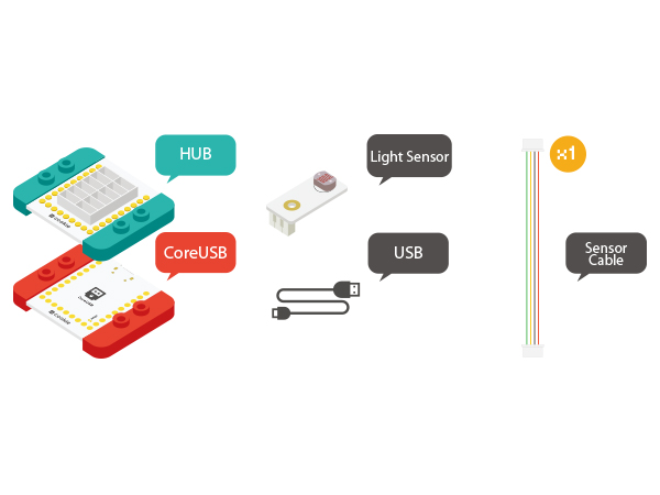
Module Number Function
mCookie-CoreUSB 1 Core board
mCookie-Hub 1 Sensor pin board
Microduino-Servo Connector 1 Servo connecting plate
  • Other Hardware Equipment
    • Servo
    • A USB cable
Module-light.jpg

Preparation

  • Setup 1:Connect Microduino-Servo Connector and the servo together to the last row of pins.
MCookie-Servo Connector-sensor.JPG
  • Setup 2:Connect the Microduino-Servo Connector and the Hub's analog port IIC.
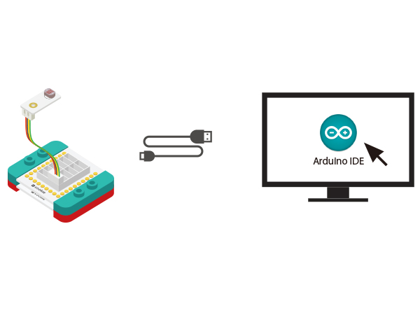
  • Setup 3:Connect all equipment to the computer with a USB cable.
MCookie-Light-pc.JPG

Experiment One: Drive the Servo

  • Open Arduino IDE and copy the following code into IDE.
#include <Servo.h>

Servo myservo;  // create servo object to control a servo
// a maximum of eight servo objects can be created

#define servo_pin SDA

int pos = 0;    // variable to store the servo position

void setup()
{
  myservo.attach(servo_pin);  // attaches the servo on pin SDA to the servo object
}


void loop()
{
  for (pos = 0; pos <= 180; pos += 1) // goes from 0 degrees to 180 degrees
  { // in steps of 1 degree
    myservo.write(pos);              // tell servo to go to position in variable 'pos'
    delay(15);                       // waits 15ms for the servo to reach the position
  }
  for (pos = 180; pos >= 0; pos -= 1) // goes from 180 degrees to 0 degrees
  {
    myservo.write(pos);              // tell servo to go to position in variable 'pos'
    delay(15);                       // waits 15ms for the servo to reach the position
  }
}
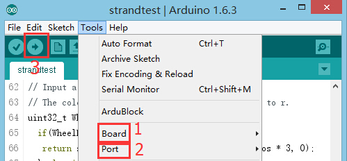
  • Select the right port from (Tools)→(Serial Port) in Arduino ID after compiling and then download program.
Upload.JPG
  • After the download, you can see the servo rotate by angle circularly.

Program Debugging

  • Adopt Servo driving library in Arduino and you can find Servo.h files here.
  • Define driving servo pin in "setup" function: “myservo.attach(servo_pin);”
  • Control the servo to rotate to a specified angle through“myservo.write(pos);”
  • Adopt "for" loop to realize automatic change of the angle. The value of "for" loop is within 0-180, which can be changed by users.
  • Adopt "delay" function to control rotation rate, which also can be changed by users to see the different results.

Experiment One: Drive the Servo

  • Open Arduino IDE and copy the following code into IDE.
#include <Servo.h>

Servo myservo;  // create servo object to control a servo
// a maximum of eight servo objects can be created

#define servo_pin SDA

String inString = "";

int pos = 0;    // variable to store the servo position

void setup()
{
  Serial.begin(9600);
  myservo.attach(servo_pin);  // attaches the servo on pin 9 to the servo object
  while (!Serial) {
    ; // wait for serial port to connect. Needed for Leonardo only
  }
}


void loop()
{
  while (Serial.available() > 0)
  {
    inString += char(Serial.read());
    delay(2);
  }
  if (inString.length() > 0)
  {
    myservo.write(inString.toInt());
    Serial.println(inString.toInt());
  }
  inString = "";
}
  • Select the right port from (Tools)→(Serial Port) in Arduino ID after compiling and then download program.
Upload.JPG
  • Open the serial monitor after download and enter any angle(0-180) in the serial input box, then click "Send".
  • Result: You can precisely control rotation angle of the servo through the serial port.

Program Debugging

  • Serial port receives data and transfers them into character string.
  while (Serial.available() > 0)
  {
    inString += char(Serial.read());
    delay(2);
  }
  • Control the servo when there is data input
  if (inString.length() > 0)
  {
    myservo.write(inString.toInt());
    Serial.println(inString.toInt());
  }
  • Since the data of the character string keeps accumulated, it needs to clear the previous data every time it receives new data. "" inString = "";

Application

Video