Self-Balancing Robot Kit: Quickstart Guide
From Microduino Wiki
This quick start guide is intended to get the reader started with the Self-Balancing Robot kit.
This guide will cover the following:
- Setting up the programming software.
- Programming and assembling the Self-Balancing Robot.
- Downloading the app and basic usage of the Self-Balancing Robot.
Contents
Software Setup
Please follow the guide to ensure your software is correctly setup. The software is required to program the Self-Balancing Robot.
Download the latest software for your operating system and follow the getting started guides:


Programming the Self-Balancing Robot
In the Self-Balancing Robot kit should be two modules of interest:
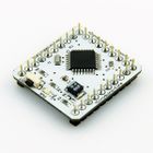
- Microduino Core - the brains of the Self-Balancing Robot. A tiny CPU which is capable of processing motion data in order to balance.
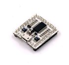
- Microduino USBTTL - programmer which writes the program from your computer to the Microduino Core module.
The Microduino Core must be programmed with the "Self-Balancing Robot" code using the Microduino USBTTL.
- Download the code for the Self-Balancing Robot: File:BalanceCar Microduino.zip
- Extract the .zip folder somewhere. Ensure, you know where the folder is as you will need to navigate to it.
- Open the Arduino for Microduino software (follow the #Software Setup section if you have not yet).
- In the software, go to File > Open... and navigate to the extracted folder. Select and open the BalanceCar_Microduino.ino file. The code should now appear in the software.
- Configure the software to program the Core module:
- Tools > Board and select Microduino/mCookie-device.
- Tools > Processor and select Microduino/mCookie-Core (328p)@16M,5V
- Stack the Microduino Core module onto the Microduino USBTTL module. Plug one end of the MicroUSB into the Microduino USBTTL and the other end to the computer.
- Go back to the software and select the port:
- Tools > Port and select what is usually selectable. (Note: if on Mac, the port is NOT the Bluetooth ones.)
- Now upload the program by click on the Right Arrow icon on the top left of the software. This is the upload button. Wait for the code to compile and then uploading will proceed. The software will inform once uploading is done on the bottom left.
- Disconnect the MicroUSB cable from the Microduino USBTTL. Separate (unstack) the two modules (Core and USBTTL).
- Note: Please be careful when separating the boards as the pins can be damaged. It is recommended to use a flat object to slowly lever one side a little, then slowly lever the other side a little, repeating until the modules separate easily.
- Place the Microduino USBTTL module aside.
| IMPORANT: The Microduino USBTTL and Microduino BT (Bluetooth) cannot be stacked at the same time. These modules utilize the same pins to communicate with the Core module. Thus, if both are active there will be unexpected behavior.
|
Self-Balancing Robot Assembly
Bill of Modules (Bluetooth Mode)
| Module | Number | Function |
| Microduino-Core | 1 | Core board |
| Microduino-USBTTL | 1 | Flash program |
| Microduino-BT | 1 | Wireless communication |
| Microduino-Motion | 1 | Motion detection |
| Microduino-Stepper | 1 | Motor driver board |
Other Material
| Module | Number | Function |
| 2.4G antenna | 1 | 2.4G communication |
| Fixation board | 1 | For fixation and support |
| M2 nylon screw | 4 | Plate fixation |
| M2 nylon column | 4 | Plate fixation |
| M2 nylon nut | 4 | Plate fixation |
| Short copper column | 8 | Fixate the motor |
| M4 metal screw | 2 | Fixate wheels |
| 2S Li-ion battery(7.4V) | 1 | Power supply |
| Lithium battery balance charger. | 1 | Lithium battery charger |
| Micro-USB cable | 1 | Serial communication & program download |
| Axis connector | 2 | Connect the motor axis and the wheel |
| Wheel | 2 | Structure |
| Stepping motor | 2 | Drive wheels |
| Stepper cable | 2 | Connect the motor and the drive board |

See Also
- Open_Source_Self-balance_Robot_System
- Additional support contact: support@microduinoinc.com