|
Microduino-Core is an 8-bit microcontroller development board, with the core of Atmel ATmega328P and ATmega168PA series. It is a open-source, compatible-with-Arduino UNO controller module.
Compared with Arduino UNO, Microduino-core has the following features:
- It uses the U-shape 27pin Microduino interface specification, and it has multiple interface compatible peripheral modules and sensors.
- Microduino breaks up the USB serial interface communication module and Atmega core module, and makes them into two Microduino development boards which can be divided and stacked.
- It uses micro USB to supply power, and removes the external power supply socket, making the whole size very small, 25.4mm long X 27.94mm wide(the size of a 1 yuan coin).
Lightweight design makes Microduino has a unique advantage in the project designs with the requirement of size and cost, and it can achieve the fast and flexible function extension for the design with other Microduino modules, according to the need of the players.
Microduino uses java and C language development environment, same as Arduino. The players can use Arduino IDE, together with software such as Flash and Processing, use Microduino and other electronic components, modules, and sensors to make many interesting and interactive works.
Feature
- Small, cheap, stacked, and open.
- Open-source hardware circuit design, and programming development environment compatible with Arduino;
- Same as Arduino, Microduino can use ISP download line to program to「bootloader」 flexibly;
- Unified Microduino interface specification and abundant peripheral modules, can be quickly and conveniently and flexibly connected and extended with other modules and sensors conforming to the Microduino interface specification;
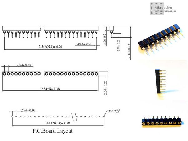
- 2.54-distance parent interface is convenient to integrate into the hole plate.
|
Specification
- According to the different core and clock frequency, there are four different versions of the Microduino-Core:
| Type
|
Flash
|
SRAM
|
EEPROM
|
Clock frequency
|
-
|
Atmega328P@16M,5V
|
32K
|
2K
|
1K
|
16M
|
5.0V
|
| ATmega328P@8M,3V3
|
32K
|
2K
|
1K
|
8M
|
3.3V
|
| ATmega168PA@16M, 5V
|
16K
|
1K
|
512
|
16M
|
5.0V
|
| ATmega168PA@8M, 3V3
|
16K
|
1K
|
512
|
8M
|
3.3V
|
- The size of Microduino: 25.4mm X 27.94mm .
- Digital I/O There are 22 digital input/output ports totally:
- They are labeled on the module of D0, D1, D2~D13, and A0~A7, of which A6 and A7 can only input.
- Analog I/O There are 8 analog input ports totally:
- They are labeled on the module of A0~A7;
- Each of them offers 10 resolution(namely 0~1024). By default, the analog voltage range for measurement is GND to VCC voltage values;
- Please refer to analogRead()' function for the details.
- PWM supports, a total of 6:
- Respectively labeled on the module of D3,D5,D6,D9,D10,D11.
- Please refer to analogWrite() function for the details.
- A serial port support, a total of 1:
- Labeled on the module of Serial[D0(RX), D1(TX)]
- If it connects with USBTTL module, it will take D0 and D1. If ports D0 and D1 are also be taken by other modules, it will communicate with USBTTL abnormal, and the program will not be able to download.
- SPI support, a total of 1:
- Labeled on the module of D13(SCK), D12(MISO), D11(MOSI), D10(SS).
- I2C support, a total of 1:
- Labeled on the module of SDA(A4), SCL(A5).
- External interrupt support, a total of 2:
- Labeled on the module of D2(interrupt0), D3(interrupt1).
- Please refer to theattachInterrupt() function for the details.
- It supports the ISP download function.
- It supports the AREF end.
| Pin
|
Original Pin Name
|
Map Pin Name
|
Digital Pin
|
Analog Pin
|
interrupt
|
PWM
|
Serial
|
SPI
|
I2C
|
Power
|
| 1 |
VCC |
+5V |
|
|
|
|
|
|
|
+5V
|
| 2 |
VCC |
+3V3 |
|
|
|
|
|
|
|
+3.3V
|
| 3 |
(AIN1)PD7 |
D7 |
D7 |
|
|
|
|
|
|
|
| 4 |
(ICP)PB0 |
D8 |
D8 |
|
|
|
|
|
|
|
| 5 |
(OC1A)PB1 |
D9 |
D9 |
|
|
yes |
|
|
|
|
| 6 |
(OC1B/SS)PB2 |
D10 |
D10 |
|
|
yes |
|
SS |
|
|
| 7 |
(OC2A/MOSI)PB3 |
D11 |
D11 |
|
|
yes |
|
MOSI |
|
|
| 8 |
(MISO)PB4 |
D12 |
D12 |
|
|
|
|
MISO |
|
|
| 9 |
(SCK)PB5 |
D13 |
D13 |
|
|
|
|
SCK |
|
|
| 10 |
AREF |
AREF |
|
|
|
|
|
|
|
|
| 11 |
(ADC0)PC0 |
A0 |
D14 |
A0 |
|
|
|
|
|
|
| 12 |
(ADC1)PC1 |
A1 |
D15 |
A1 |
|
|
|
|
|
|
| 13 |
(ADC2)PC2 |
A2 |
D16 |
A2 |
|
|
|
|
|
|
| 14 |
(ADC3)PC3 |
A3 |
D17 |
A3 |
|
|
|
|
|
|
| 15 |
(ADC4/SDA)PC4 |
SDA |
D18 |
A4 |
|
|
|
|
SDA |
|
| 16 |
(ADC5/SCL)PC5 |
SCL |
D19 |
A5 |
|
|
|
|
SCL |
|
| 17 |
(ADC6) |
A6 |
D20(only input) |
A6 |
|
|
|
|
|
|
| 18 |
(ADC7) |
A7 |
D21(only input) |
A7 |
|
|
|
|
|
|
| 19 |
(RXD)PD0 |
D0 |
D0 |
|
|
|
0(RX) |
|
|
|
| 20 |
(TXD)PD1 |
D1 |
D1 |
|
|
|
0(TX) |
|
|
|
| 21 |
(INT0)PD2 |
D2 |
D2 |
|
0 |
|
|
|
|
|
| 22 |
(OC2B/INT1)PD3 |
D3 |
D3 |
|
1 |
yes |
|
|
|
|
| 23 |
(XCK/T0)PD4 |
D4 |
D4 |
|
|
|
|
|
|
|
| 24 |
(OC0B/T1)PD5 |
D5 |
D5 |
|
|
yes |
|
|
|
|
| 25 |
(OC0A/AIN0)PD6 |
D6 |
D6 |
|
|
yes |
|
|
|
|
| 26 |
RESET |
RST |
|
|
|
|
|
|
|
|
| 27 |
GND |
GND |
|
|
|
|
|
|
|
GND
|
|
Document
Eagle PCB File:Microduino-Core.zip
- The main components used in Microduino-core.
|
Development
- 1.Developing program to Microduino-core, players need to use Microduino-USBTTL module.
- 2.The tutorial of setting up the development environment and installing the driver is as following:
- Program Microduino BootLoader.
- If you get a Microduin-Core empty board, you need to use Arduino UNO or the existing Microduino to program bootloader for another Microduino empty board. You can refer to the tutorial Do you know how to use Arduino UNO to program bootloader to Microduino-Core?.
- Each version of Microduino-Core uses different bootloader, and the initial bootloader is the bootloader that the optiboot aims at ATmegaX8 set, and it takes 512 bytes flash space.
|
Application
|
FAQ
- Q:How can I judge the voltage of my Core is 3.3V or 5V?
- A:By the resistor. If the R1 is soldered, it is 3.3V, and if R2 is soldered, it is 5V.
- Q:Can I supply power to the Core+ of 16M color frequency with 3.3V?
- A:It is not recommended. If the voltage is too low, it will be easy to be unstable.
- Q:Can I use 5V voltage to supply power to the core of 8M clock frequency?
Acquisition
|
Map Storage
 Microduino-core Upin27 model
History
- On December 16, 2012, the Arduino IDE support service pack for Microduino Core is published. Refer to Install Arduino IDE Microduino hardware support package for the detail.
- On November 18, 2012, the first released version was determined. Cut down some functions, maintain the minimum system of lean, reduce the cost and adopt beautiful manual wiring appearance.
|
|
|


