Microduino-Module CoreRF

From Microduino Wiki
(Redirected from Microduino-CoreRF)
Jump to: navigation, search
Language: English  • 中文
Microduino-CoreRF

Microduino CoreRF is an AVR core board with 802.15.4 Wireless Protocol integrated. It supports any wireless modules based on 802.15.4 Protocol, including Zigbee, MAC/6LoWPAN and RF4CE.

Features

  • Integrate 802.15.4 Wireless Protocol and support wireless modules like Zigbee, MAC/6LoWPAN and RF4CE.
  • Small, open, stackable and economic.
  • With open source hardware circuit design and Arduino compatible programming IDE.
  • Like Arduino, Microduino can use ISP download method to burn programs into「bootloader」flexibly.
  • With uniform Microduino interface standard and rich peripheral modules, it can easily connect with other Microduino modules and sensors.
  • 2.54mm (0.1 inch) pin pitch, compatible with breadboards and pegboards.

Specification

Adopt ATmega128RFA1 core chip

Power supply 3.3 V
Flash 128 KB
SRAM 16 KB
EEPROM 4 KB
Frequency of the time clock 16 MHz


  • 22 digital I/O ports (6 of them supports ADC):
  • 2-channel hard serial port:
    • UART0_RX: D0
    • UART0_TX: D1
    • UART1_RX: D2
    • UART1_TX: D3
  • Support 7-channel PWM:
    • D4, D5, D6, D7, D8, D9, D10
  • 6-channel external interrupt:
    • Interrupt0 (pin SCL)
    • Interrupt1 (pin SDA)
    • Interrupt2 (pin D2)
    • Interrupt3 (pin D3)
    • Interrupt4 (pin D5)
    • Interrupt5 (pin D6)
  • 10 Analog I/O ports:
    • In the module, it is marked with A0, A1, A2, A3, A6, A7, D8(A8), D9(A9), D3(A10) and D4(A11).
    • Each offers 10-bit resolution(0-1024). The measurement range of the analog voltage is from GND to VCC by default.
    • For more information, please refer to analogRead().
  • Support 1-channel SPI:
    • In the module, it's marked with D13(SCK), D12(MISO), D11(MOSI), D10(SS).
  • Support 1-channel IIC:
    • In the module, it is marked with SDA(D18), SCL(D19).


  • Pin Description:
Pin Original Pin Name Map Pin Name Digital Pin Analog Pin interrupt PWM Serial SPI I2C Power
1 VCC +5V +5V
2 VCC +3V3 +3.3V
3 (OC0A/OC1C)PB7 D7 D7 yes
4 (OC1B)PB6 D8 D8 yes
5 (OC1A)PB5 D9 D9 yes
6 (OC2A/SS)PB4 D10 D10 yes SS
7 (PDI/MOSI)PB2 D11 D11 MOSI
8 (PDO/MISO)PB3 D12 D12 MISO
9 (SCK)PB1 D13 D13 SCK
10 AREF AREF
11 (ADC7)PF7 A0 D14 A0
12 (ADC6)PF6 A1 D15 A1
13 (ADC5)PF5 A2 D16 A2
14 (ADC4)PF4 A3 D17 A3
15 (SDA)PD1 SDA D18 1 SDA
16 (SCL)PD0 SCL D19 0 SCL
17 (ADC3)PF3 A6 D20 A6
18 (ADC2)PF2 A7 D21 A7
19 (RXD0)PE0 RX0 D0 0(RX)
20 (TXD0)PE1 TX1 D1 0(RX)
21 (RXD1)PD2 D2 D2 2 1(RX)
22 (TXD1)PD3 D3 D3 3 1(TX)
23 (OC3A)PE3 D4 D4 yes
24 (OC3B)PE4 D5 D5 4 yes
25 (OC3C)PE5 D6 D6 5 yes
26 RESET RST
27 GND GND GND
Microduino-CoreRF引脚
Microduino-CoreRF元件

Document

  • Eagle PCB

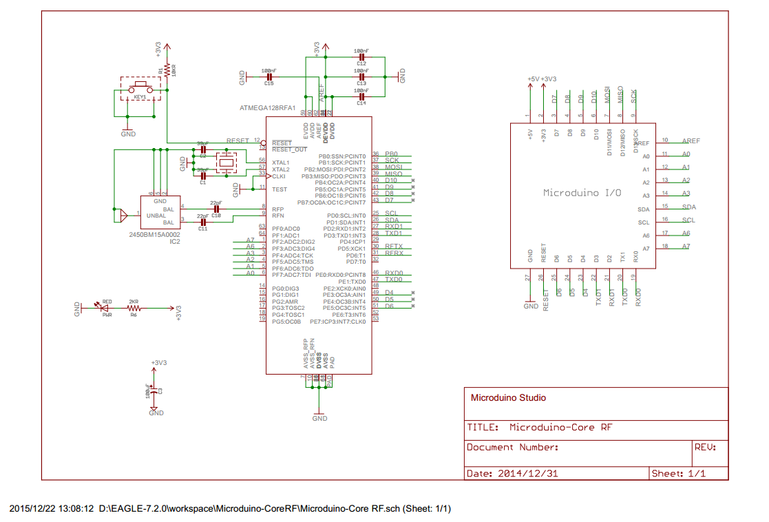
Schematic of CoreRF: 【CoreRF schematic diagram


  • Main components used in Microduino CoreRF

ATmega128RFA1: http://www.atmel.com/zh/cn/devices/ATMEGA128RFA1.aspx?tab=documents

Development

Project

Microduino-Quadcopter Tutorial

Test

Use program examples in ZigduinoRadio library to test.

void loop() 
{ 
    if (Serial.available()) 
    { 
        ZigduinoRadio.beginTransmission(); 
 
        Serial.println(); 
        Serial.print("Tx: "); 
 
        while(Serial.available()) 
        { 
            char c = Serial.read(); 
            Serial.write(c); 
            ZigduinoRadio.write(c); 
        } 
 
        Serial.println(); 
 
        ZigduinoRadio.endTransmission(); 
    } 
 
    if (ZigduinoRadio.available()) 
    { 
        Serial.println(); 
        Serial.print("Rx: "); 
 
        while(ZigduinoRadio.available()) 
            Serial.write(ZigduinoRadio.read()); 
 
        Serial.println(); 
        Serial.print("LQI: "); 
        Serial.print(ZigduinoRadio.getLqi(), 10); 
        Serial.print(", RSSI: "); 
        Serial.print(ZigduinoRadio.getLastRssi(), 10); 
        Serial.print(" dBm, ED: "); 
        Serial.print(ZigduinoRadio.getLastEd(), 10); 
        Serial.println("dBm"); 
    } 
 
    delay(100); 
} 
 
void errHandle(radio_error_t err) 
{ 
    Serial.println(); 
    Serial.print("Error: "); 
    Serial.print((uint8_t)err, 10); 
    Serial.println(); 
} 
 
void onXmitDone(radio_tx_done_t x) 
{ 
    Serial.println(); 
    Serial.print("TxDone: "); 
    Serial.print((uint8_t)x, 10); 
    Serial.println(); 
}

This example realizes wireless serial transmission function. Since the CoreRF adopts serial port download, you need firstly stack a Microduino-USBTTL on it: Choose Microduino CoreRF as the board card

154343ch79m113a77932i7.jpg

Open the serial monitor after uploading programs to the two Core-RF modules, input " Hello Microduino!", click "Send" and you'll get the following result:

Result.png
Result1.png

By here, we've completed the test.

FAQ

Purchase

History

Picture

  • Front
Front
  • Back
Back

Video