Microduino Number Selecting and Text Messaging through the Key
Outline
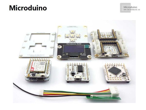
Bill of Materials
DocumentOLED drive library download: https://github.com/Microduino/Microduino_Tutorials/tree/master/Microduino_Libraries/_01_Microduino_OLED_MultiLCD Example Program Download: https://github.com/Microduino/Microduino_Tutorials/commit/80ae5bd5ef867643fb8f22ef250dbf6dfecbf47b Debugging
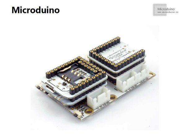
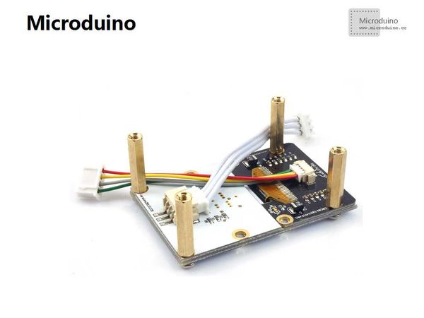
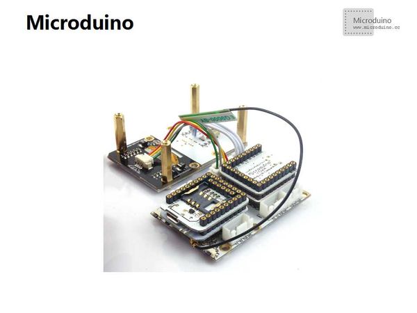
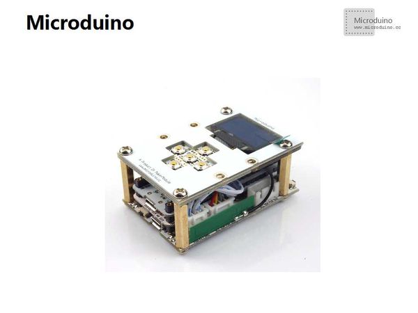
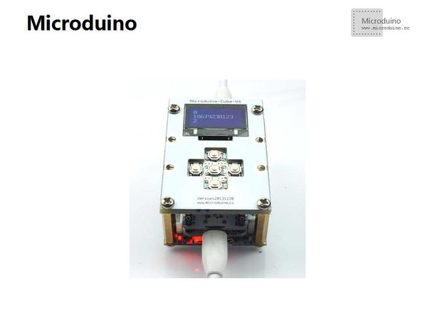
Stack modules needed to the UPIN27 base of Microduino-Cube-V1 You need to connect Microduino-OLED to the IIC interface of the base through the connector and connect the simulated control panel to the corresponding simulated button interface of the base through jumpers. (The simulated interface can be detected through A7 pin.) Build up the whole circuit.
There are two ways to supply power for Microduino-GPRS/GSM, including power supply by the micro USB cable and by Li-ion battery. Just choose one you like.
The initializing number: Users can change the number as they like and store it into the array. byte num[12] =
{
1, 8, 6, 7, 9, 2, 3, 8, 1, 2, 3
};The fixed short message: Users can change it as they like and save it into the character strings. #define text "Hello! @Microduino"Sending short messages through AT instructions void SMS_sms(byte *c_num, char *c_text)
{
Serial1.print("AT+CMGF=1\r");
//Because we want to send the SMS in text mode
delay(100);
while(Serial1.available()) Serial.write(Serial1.read());
Serial1.print("AT+CMGS=\"+86");
for(int a = 0; a < 11; a++)
Serial1.print(c_num[a]);
Serial1.println("\"");
delay(100);
Serial1.println(c_text);//the content of the message
delay(100);
Serial1.println((char)26);//the ASCII code of the ctrl+z is 26
delay(100);
Serial1.println();
while(Serial1.available()) Serial.write(Serial1.read());
}System TestStep 1: Make sure the hardware buildup is right
Step 2: Start Microduino-GPRS/GSM
Step 3: Download the program
Step 4: Set the number
Step 5: Send the short message
Test &Verify
Notice
|
