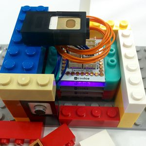
Sound Sensitive LED Project (X02)
About
This project uses the Microphone to detect sounds. Based on the sound levels, it maps the loudness to the LED Matrix's brightness. Visually see the loudness of the surrounding sound on the LED Matrix!
Color of the LED Matrix can be adjust between 7 colors with the touch button.
This project was designed for the second generation mCookie Maker kits (102 Basic, 202 Advanced and 302 Expert kits).
Required Materials
- 1 x mCookie Core
- 1 x mCookie USB TTL (102 Kit) or 1 x mBattery (202/302 Kit)
- 1 x mCookie Sensor Hub
- 1 x mCooke LED Matrix
- 1 x Microphone Sensor
- 1 x Touch Button
- 2 x Sensor Cable
- 1 x MicroUSB Cable
Build
NOTE: When connecting sensor wires, push on the plastic connector and not on the wires. Pushing on the wire can damage them.
- Connect the Microphone Sensor to the Sensor Hub on Pin A2/A3
- Connect the Touch Button to the Sensor Hub on Pin 6/7
- Grab the mCookie USBTTL or mBattery and Stack the mCookie Core on top.
- Stack the mCookie LED Matrix on top of that.
- Stack the mCookie Sensor on top of that.
- Plug in the MicroUSB cable to the mCookie USBTTL or mBattery to a computer.
Program
1. Connect mCookie Core to the PC with the USB Cable. Open the Microduino IDE.
2. Download the project file and unzip: File:Sound Sensitive LED X02.zip.
- Using the Microduino IDE and go to File > Open... and navigate to the unzipped folder. Open the Sound_Sensitive_LED_X02.ino file.
3. Select the board, processor and port:
- Go to Tools > Board and select Microduino/mCookie-Core (328p)
- Go to Tools > Processor and select Atmega328P16M,5V
- Go to Tools > Port and select the available port
4. Upload the program by clicking on the right arrow icon on the top left of the window. Or under Sketch > Upload.
NOTE: If not using the default Core module included in the kits, please follow the selecting the board and processor guide.
Debugging
- Uncomment the DEBUG. Re-upload the sketch with that modification.
- Open the Serial monitor. It should start printing the raw Microphone values. These values can be used to tweak the sketch to better suit your environment.
- Note: Change DEBUG back to 0 and re-upload the sketch when debugging is done. With debug mode on there is an added delay when reading Microphone values. Therefore, the light transitions may not seem as smooth when debugging is on.
Tweaking
Variables can be edited to change the threshold / detection value for various functions to better fine tune to your environment.
DEBUG will enable or disable debugging.
LEDMATRIX_PIN defines the pin that connects the LED Matrix
NUMPIXELS defines the number of pixels on the LED Matrix
MIC_PIN defines the pin that connects to the Microphone
TOUCH_PIN defines the pin that connects the Touch Button
AMBIENT_THRESHOLD will change the value that is registered as ambient noise when reading from the Microphone. A lower value is less ambient noise, higher value is louder ambient noise. Values can be retrieved during debugging mode.
- Adjustable between 0 ~ 1023
- Default value is 40
MAX_THRESHOLD will change maximum value the Microphone can register. This is useful to narrow the noise level range and produce a better brightness range. Values can be retrieved during debugging mode.
- Default value is 800
- Adjustable between 0 ~ 1023
DEBOUNCE_TIME_MILLISECONDS will set the time to hold down the touch button to register as a "press"
Usage
Talk or play music towards the Microphone and the LED Matrix should react to the noise loudness. Change the color of the LED Matrix by pressing the Touch Button. There 7 select-able colors. There is a 200 millisecond (1/5 second) delay between Touch Button detection.
