Difference between revisions of "Light Indicator"
From Microduino Wiki
(→Software Debuggin) |
|||
| (One intermediate revision by one other user not shown) | |||
| Line 1: | Line 1: | ||
| − | {{Language|Light Indicator}} | + | {{Language| Light Indicator}} |
{| style="width: 800px;" | {| style="width: 800px;" | ||
|- | |- | ||
| | | | ||
==Objective== | ==Objective== | ||
| − | Here we make a simple light indicator, which divides light value into three levels, that is, green, blue and red. | + | Here we make a simple light indicator, which divides light value into three levels, that is, green, blue and red. [[File:light_indicator-ok.jpg|600px|center]] |
==Principle== | ==Principle== | ||
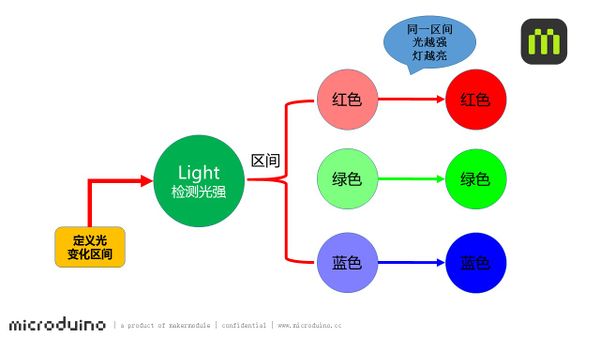
| + | We adopt the Light sensor to detect the light intensity. The system can judge which range the light intensity lies and let the LED present the corresponding color. In the same range, the color gets brighter along with the light intensity increases. | ||
| + | [[File:light_indicator-sch.jpg|600px|center]] | ||
==Equipment== | ==Equipment== | ||
| Line 19: | Line 21: | ||
|[[Microduino-Light]]||1||light-sensitive sensor | |[[Microduino-Light]]||1||light-sensitive sensor | ||
|- | |- | ||
| − | |[[Microduino- | + | |[[Microduino-Color LED]]||1||Colored led light |
|- | |- | ||
| [[Microduino-BM]]||1||Battery management | | [[Microduino-BM]]||1||Battery management | ||
|} | |} | ||
| + | [[File:light_indicator-module.jpg|600px|center]] | ||
| − | + | ==Preparation== | |
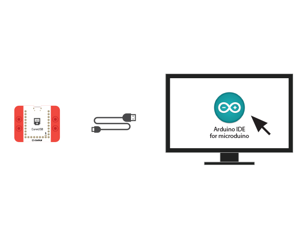
| − | + | *Setup 1: Use a USB cable to connect the CoreUSB and the PC/Mac, the open Arduino IDE. [[File:CoreUSB_Ble_pc.jpg|600px|center]] | |
| − | + | *Setup 2: Download the program: | |
| − | *Setup | ||
[https://github.com/Microduino/Microduino_Tutorials/blob/master/MCookie_Tutorial/light_led/light_led.ino light_led] | [https://github.com/Microduino/Microduino_Tutorials/blob/master/MCookie_Tutorial/light_led/light_led.ino light_led] | ||
| − | + | [[File: light_indicator-load.jpg|600px|center]] | |
| − | [[ | + | * Setup 3: Load the code, choose the right board and COM port for program download after compiling. |
| − | + | ==Program Description== | |
| − | * | + | *Pin Definition of the sensor: The Color LED connects to D6 and the Light sensor connects to A0. |
| − | |||
| − | |||
| − | |||
| − | |||
| − | == | ||
| − | |||
| − | |||
<source lang="cpp"> | <source lang="cpp"> | ||
#define PIN 6 | #define PIN 6 | ||
| Line 46: | Line 41: | ||
#define Light_PIN A0 | #define Light_PIN A0 | ||
</source> | </source> | ||
| − | *Light intensity pre-set | + | *Light intensity pre-set values: You can classify the light into three levels. |
<source lang="cpp"> | <source lang="cpp"> | ||
#define Light_value1 400 | #define Light_value1 400 | ||
| Line 57: | Line 52: | ||
</source> | </source> | ||
| − | *The | + | *The Color LED can adjust color and brightness according to light intensity. |
<source lang="cpp"> | <source lang="cpp"> | ||
if (sensorValue < Light_value1) | if (sensorValue < Light_value1) | ||
| Line 66: | Line 61: | ||
colorWipe(strip.Color(map(sensorValue, 800, 960, 0, 255), 0, 0)); | colorWipe(strip.Color(map(sensorValue, 800, 960, 0, 255), 0, 0)); | ||
</source> | </source> | ||
| + | *"map(val,x,y,m,n)"is the reflection function, which can reflect the (x-y) value of a certain range to (m-n). "val" is the data that you need to reflect. | ||
| + | ==Hardware Buildup== | ||
| + | *Setup 1: Connect the photosensitive resistor to the A0 pin of the Sensorhub and the Color LED to D6. | ||
| + | [[file: light_indicator _A0_6.JPG|800px|center]] | ||
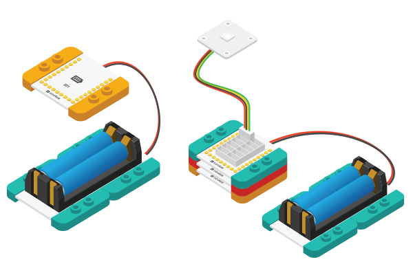
| + | *Setup 2: Connect the activated battery box and the BM module. | ||
| + | [[File:CoreUSB_Ble_steup2.jpg|600px|center]] | ||
| + | *Setup 3: Then, stack all modules together without considering order. Congratulations! You've finished the circuit buildup. | ||
| + | [[File: ight_indicator_steup-all.jpg|600px|center]] | ||
==Result== | ==Result== | ||
| − | + | By changing the light environment, the light from dark to bright colors are changed to green - blue - red, and the weaker the light is, the lower the brightness becomes. | |
| − | + | You can also build a beautiful look for this project through Lego boards. | |
==Video== | ==Video== | ||
|} | |} | ||
Latest revision as of 06:57, 30 September 2016
| Language: | English • 中文 |
|---|
ContentsObjectiveHere we make a simple light indicator, which divides light value into three levels, that is, green, blue and red.PrincipleWe adopt the Light sensor to detect the light intensity. The system can judge which range the light intensity lies and let the LED present the corresponding color. In the same range, the color gets brighter along with the light intensity increases. Equipment
Preparation
Program Description
#define PIN 6
Adafruit_NeoPixel strip = Adafruit_NeoPixel(1, PIN, NEO_GRB + NEO_KHZ800);

#define Light_PIN A0
#define Light_value1 400
#define Light_value2 800
sensorValue = analogRead(Light_PIN);
if (sensorValue < Light_value1)
    colorWipe(strip.Color(0, map(sensorValue, 10, 400, 0, 255), 0));
  else if (sensorValue >= Light_value1 && sensorValue < Light_value2)
    colorWipe(strip.Color(0, 0, map(sensorValue, 400, 800, 0, 255)));
  else if (Light_value2 >= 800)
    colorWipe(strip.Color(map(sensorValue, 800, 960, 0, 255), 0, 0));
Hardware Buildup
ResultBy changing the light environment, the light from dark to bright colors are changed to green - blue - red, and the weaker the light is, the lower the brightness becomes. You can also build a beautiful look for this project through Lego boards. Video |


