Difference between revisions of "MCookie-Hub"
From Microduino Wiki
(→Specification) |
(→Pin Description) |
||
| Line 31: | Line 31: | ||
===Pin Description=== | ===Pin Description=== | ||
| + | Most sensors use the first signal (signal 1) when connecting to the sensor hub. | ||
| + | |||
| + | {| class="wikitable" | ||
| + | |- | ||
| + | ! | ||
| + | ! PinOut A | ||
| + | ! PinOut B | ||
| + | ! PinOut C | ||
| + | ! PinOutD | ||
| + | |- | ||
| + | ! Hub Header | ||
| + | | GND | ||
| + | | VCC | ||
| + | | SIGNAL 1 | ||
| + | | SIGNAL 2 | ||
| + | |- | ||
| + | ! ST* Connector | ||
| + | | GND | ||
| + | | VCC | ||
| + | | INPUT / OUTPUT | ||
| + | | Not connected (usually) | ||
| + | |} | ||
| + | *ST = Sensor / Trinket Connector | ||
| + | |||
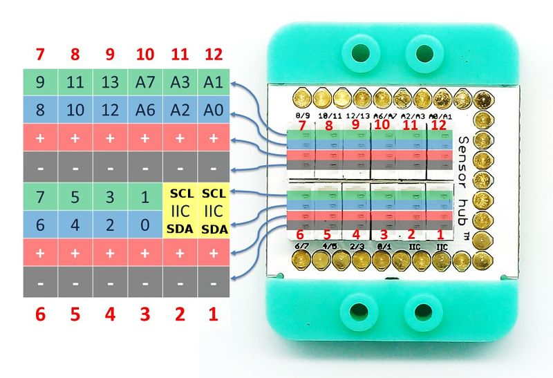
Sensor interface rules: '''GND, VCC, signal 1 and signal 2 ''' or '''GND, VCC, signal 1 and NC(empty)'''. | Sensor interface rules: '''GND, VCC, signal 1 and signal 2 ''' or '''GND, VCC, signal 1 and NC(empty)'''. | ||
Hub interface rules: '''GND, VCC, signal 1 and signal 2 '''. | Hub interface rules: '''GND, VCC, signal 1 and signal 2 '''. | ||
Revision as of 21:29, 29 March 2017
| Language: | English • 中文 |
|---|
|
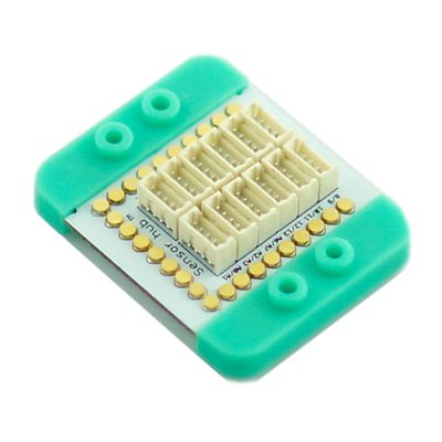
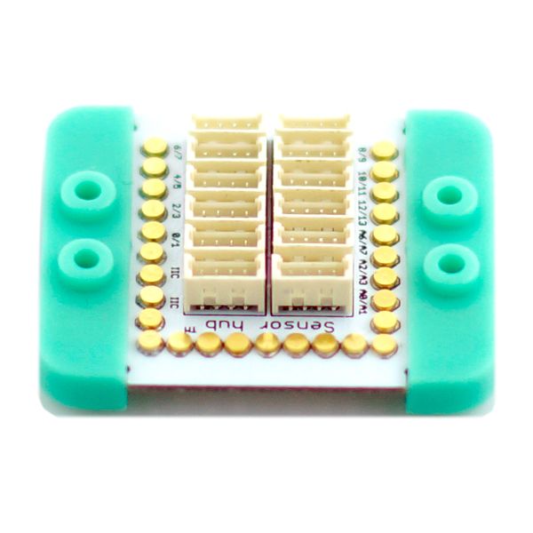
mCookie-Hub is designed for ease of the connection between Microduino Sensor Series and the core modules on the UPIN27 base board as well as further extended experiment. The sensor / trinket connector are 4 pin, 1.25mm pitch JST connectors.
ContentsFeatures
Specification
Pin DescriptionMost sensors use the first signal (signal 1) when connecting to the sensor hub.
Sensor interface rules: GND, VCC, signal 1 and signal 2 or GND, VCC, signal 1 and NC(empty). Hub interface rules: GND, VCC, signal 1 and signal 2 .
DocumentDevelopment
ProjectPurchaseHistoryPicturesVideo |


