|
mCookie-Hub is designed for ease of the connection between Microduino Sensor Series and the core modules on the UPIN27 base board as well as further extended experiment.
Features
- Integrate twelve sensor interfaces;
- Small size with sensor interface integrated on the Upin 27 base board;
- All function pins are extended;
- Prevent reverse sensor connection
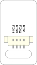
- Uses 4 pin, 1.25mm pitch JST headers
Specification
- All mCookie function pins are connected to the base board of the Hub, including digital, analog, serial port and IIC interface.
- Hub's interface pinout per header: GND, VCC, GPIO-A and GPIO-B.
- Two IIC interfaces.
- Uses 4 pin, 1.25mm pitch JST headers / connectors.
Pin Description
Most sensors / trinkets use the first signal (SIGNAL-A) when connecting to the sensor hub.
Hub to Sensor / Trinket Connection Mapping
| Hub Header
|
Sensor / Trinket's Connector
|
| GND ( - )
|
(PIN1) GND
|
| VCC ( + )
|
(PIN2) VCC
|
| GPIO-A
|
(PIN3) SIGNAL-A -- INPUT / OUTPUT (usually)
|
| GPIO-B
|
(PIN4) SIGNAL-B -- Not connected (usually)
|
- Therefore, when referencing the sensor / trinket in code. Use the first number (GPIO-A) on the labeled header. See examples below.
- Some modules use both signals A & B, but they are limited.
- Please refer to the specific sensor / trinket page for more detailed information on a specific one.
- In order to use the second signal. An IO split is used to split the signals out into two separate connectors. More can be read about the IO split: IO Split
- IIC (I2C) uses both signals, but these headers are strictly for IIC communication.
Header & GPIO-A / GPIO-B
Mapping
| #
|
Label
|
GPIO-A
|
GPIO-B
|
| 1
|
IIC |
SDA |
SCL
|
| 2
|
IIC
|
| 3
|
0/1 |
0 |
1
|
| 4
|
2/3 |
2 |
3
|
| 5
|
4/5 |
4 |
5
|
| 6
|
6/7 |
6 |
7
|
| 7
|
8/9 |
8 |
9
|
| 8
|
10/11 |
10 |
11
|
| 9
|
12/13 |
12 |
13
|
| 10
|
A6/A7 |
A6 |
A7
|
| 11
|
A2/A3 |
A2 |
A3
|
| 12
|
A0/A1 |
A0 |
A1
|
Example
- With a Light Sensor that is plugged into the A2/A3 header. Use A2 to access the light sensor. (On the A2/A3 header: GPIO-A=A2; GPIO-B=A3)
- With an Single Color LED that is plugged into the 6/7 header. Use 6 to control the LED. (On the 6/7 header: GPIO-A=6; GPIO-B=7)
Each sensor / trinket page has more specific details to which pins are used, but the general rule is use the first signal (SIGNAL-A).
Each sensor / trinket may require usage of a specific type of pin, such as an analog pin. This information can be found on the wiki page for that specific sensor / trinket.
Document
Development
- Stack with Microduino core modules and have an external connection with Microduino sensors. Select the right interface according to different sensors.
Project
Purchase
History
Pictures
Video
|


