Difference between revisions of "Sensor-Color LED"
From Microduino Wiki
(→Program) |
|||
| Line 5: | Line 5: | ||
[[File: Microduino-WS2812-rect-v1.jpg|400px|thumb|right| Microduino-Color led]] | [[File: Microduino-WS2812-rect-v1.jpg|400px|thumb|right| Microduino-Color led]] | ||
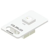
| − | + | mCookie-Color LED is a colored LED sensor with an built-in IC control chip, which can be cascaded arbitrarily. With only one I/O port, you can control all the lights and each light can be controlled separately. | |
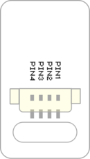
| + | ==Sensor Pin Introduction== | ||
| + | {{Sensor_explain | ||
| + | |nameA=[[Sensor-Color LED]] | ||
| + | |modeA=Digital Signal Output | ||
| + | |modeB=NC | ||
| + | }} | ||
| + | ==Feature== | ||
| + | *With single bus control. Only one I/O port to control, and complete the receiving and decoding of the data; | ||
| + | *With built-in IC controller, and serial connection interfaces, which can cascade control; | ||
| + | *The three primary colors of each pixel point can realize 256-level brightness display, and achieve 16777216-color whole true color display. And the scanning frequency is not lower than 400Hz/s; | ||
| + | *With ultra-low power and ultra-long life. | ||
| + | ==Specification== | ||
| + | *Sensor voltage | ||
| + | **3.3V~5V working voltage | ||
| + | |||
| + | *Size of the sensor | ||
| + | **Size of the board: 23.5mm*13mm | ||
| + | **1.27mm-spacing 4Pin interface connected with sensorhub; | ||
| + | **CAD drawing of the sensor: '''[[File:Sensor_CAD.zip]]''' | ||
| + | **1.27mm-spacing 4Pin interface connected with sensorhub. | ||
| + | *Function description | ||
| + | **Adopt WS2812 integrated control light source; | ||
| + | **RGB of each pixel point can achieve 256-level brightness display; | ||
| + | **When the updating rate is 30 frame/s, the cascade number is not less than 1024; | ||
| + | **When the transmission distance between any two points is not over 3 meters, don’t need to add any circuit. | ||
| + | *Connection | ||
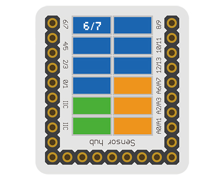
| + | **This sensor can be connected to the following interfaces of the core:'''D2~D13''' | ||
| + | **Multiple sensors cascade: Connect the '''(<big>OUT</big>)''' of the former LED—Strip to the '''(<big>IN</big>)''' of the later Color_LED. | ||
| + | ==Document== | ||
| − | + | *Schematic diagram: '''[[File: Microduino_Sensor-Color_LED.Zip.pdf]]''' | |
| − | * | + | *Crashdatasheet:'''[[File: Microduino_Sensor-Color_LED_datasheet.pdf]]''' |
| − | |||
| − | |||
| − | * | ||
| − | |||
| − | |||
| − | == | + | ==Development== |
| − | + | ===Program Download=== | |
| − | * | + | *Download and unzip the program'''[[File:Microduino_Sensor-Color_LED_Test.zip]]''' |
| − | |||
| − | |||
| − | |||
| − | |||
| − | |||
| − | |||
| − | |||
| − | |||
| − | |||
| − | |||
| − | |||
| − | |||
| − | |||
| − | [[ | + | ===Prgramming=== |
| + | {{Upload | ||
| + | |nameA=[[Microduino-Core]], [[Microduino-USBTTL]] | ||
| + | |nameB=[[Microduino-USBTTL]] | ||
| + | |boardName=Microduino/mCookie-Core(328p)、Atmega328P@16M,5V | ||
| + | |fileName=Microduino_Sensor-Color_LED_Test.ino | ||
| + | }} | ||
| − | == | + | ===Hardware Setup=== |
| − | [[ | + | *Referring to the following picture, connect Sensor-Crash to the digital port D6 of '''[[Microduino-Sensorhub]]'''. |
| + | <br> | ||
| + | [[file:Microduino-sensorhub_Shake.JPG|thumb|400px|left]] | ||
| + | <br style="clear: left"/> | ||
| − | == | + | ===Result Observation=== |
| − | + | *After the download, observe the led strip; | |
| − | + | *LED twinkles in red, and green successively with the interval of 1s. | |
| − | |||
| − | |||
| − | * | ||
| − | |||
| − | |||
| − | |||
| − | * | ||
| − | |||
| − | |||
| − | |||
| − | |||
| − | |||
| − | |||
| − | |||
| − | |||
| − | |||
| − | |||
| − | == | + | ==Application== |
| − | * | + | *LED full color light letter lamp string, LED full color module set, LED full color soft lamp strip and hard lamp strip, and LED guardrail tube. |
| − | + | *LED point light source, LED pixel screen, all kinds of electronic products, LED shaped screen, and electrical equipment Marquee. | |
| − | |||
| − | |||
| − | |||
| − | * | ||
| − | |||
| − | |||
| − | |||
==Project== | ==Project== | ||
| Line 88: | Line 84: | ||
==History== | ==History== | ||
| − | == | + | ==Gallery== |
| − | + | {| border="0" cellpadding="10" width="100%" | |
| − | [[file: | + | |- |
| − | + | |width="50%" valign="top" align="left"| | |
| − | [[file: Microduino- | + | [[file: MicroduinoColorLED-F.JPG|thumb|480px|center|mCookie-Color_LED-Front]] |
| + | |width="50%" valign="top" align="left"| | ||
| + | [[file: Microduino-ColorLED-b.JPG|thumb|480px|center|mCookie-Color_LED-Back]] | ||
| + | |} | ||
|} | |} | ||
Revision as of 06:08, 26 August 2016
| Language: | English • 中文 |
|---|
|
mCookie-Color LED is a colored LED sensor with an built-in IC control chip, which can be cascaded arbitrarily. With only one I/O port, you can control all the lights and each light can be controlled separately.
Contents[hide]Sensor Pin Introduction
Feature
Specification
Document
DevelopmentProgram Download
Prgramming
Hardware Setup
Result Observation
Application
ProjectPurchaseHistoryGallery
|


