Difference between revisions of "Sensor-Color LED"
From Microduino Wiki
(→Document) |
|||
| Line 4: | Line 4: | ||
| | | | ||
[[File: Microduino-WS2812-rect-v1.jpg|400px|thumb|right| Microduino-Color led]] | [[File: Microduino-WS2812-rect-v1.jpg|400px|thumb|right| Microduino-Color led]] | ||
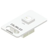
| + | The product number of Sensor-Color LED is: '''MSDL11''' | ||
| − | + | Sensor-Color LED is full color LED, adopting single serial cascade protocol. | |
| + | Only one I/O port can control the RGB color of each LED on the line. | ||
| + | If the power supply supports, it can support the cascade of as many as 1024 LEDs. | ||
| − | ==Sensor Pin | + | |
| + | |||
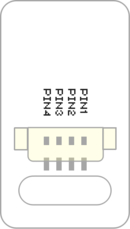
| + | ==Introduction of Sensor Pin== | ||
{{Sensor_explain | {{Sensor_explain | ||
|nameA=[[Sensor-Color LED]] | |nameA=[[Sensor-Color LED]] | ||
| − | |modeA=Digital | + | |modeA=Digital signal output |
|modeB=NC | |modeB=NC | ||
}} | }} | ||
| − | == | + | ==Features== |
| − | *With single | + | *With small size which is easy to install; |
| − | * | + | *Adopts single serial cascade protocol, which makes it cascadable; |
| − | + | *Only one I/O port can control the RGB color of each LED on the line; | |
| − | + | *Can achieve 256-grade (1600W) toning or RGB, and the scanning frequency is o less then 400Hz/s | |
| + | |||
==Specification== | ==Specification== | ||
*Sensor voltage | *Sensor voltage | ||
| − | ** | + | **5V working voltage |
| − | *Size of the sensor | + | *Size of the sensor |
**Size of the board: 23.5mm*13mm | **Size of the board: 23.5mm*13mm | ||
| − | **1.27mm-spacing 4Pin interface connected with sensorhub | + | **1.27mm-spacing 4Pin interface connected with sensorhub |
**CAD drawing of the sensor: '''[[File:Sensor_CAD.zip]]''' | **CAD drawing of the sensor: '''[[File:Sensor_CAD.zip]]''' | ||
| − | |||
*Function description | *Function description | ||
| − | ** | + | **Adopts AWS2812 lampwick |
| − | **RGB of each | + | **Adopts single serial cascade protocol, which makes it cascadable |
| − | **When the updating | + | **Only one I/O port can control the RGB color of each LED on the line |
| − | + | **Can achieve 256-grade (1600W) toning or RGB, and the scanning frequency is o less then 400Hz/s | |
| + | **When the updating speed is 30 frame/s, the cascading number is no less than 1024 | ||
*Connection | *Connection | ||
| − | **This sensor can be connected to the following interfaces of the core:'''D2~D13''' | + | **This sensor can be connected to the following interfaces of the core: '''D2~D13''' |
| − | **Multiple sensors cascade: Connect the '''(<big>OUT</big>)''' of the former | + | **Multiple sensors cascade: Connect the '''(<big>OUT</big>)''' of the former Sensor-Color LED to the '''(<big>IN</big>)''' of the latter Sensor-Color LED. |
| − | |||
| − | |||
| − | *Schematic diagram: '''[[File: Microduino_Sensor-Color_LED.Zip | + | ==Documents== |
| − | * | + | *Schematic diagram: '''[[File: Microduino_Sensor-Color_LED.Zip]]''' |
| + | *Main chip: '''[[File: WS2812.pdf]]''' | ||
| + | *You can use the sample programs in the following IDE libraries to do experiment on your own: [https://github.com/wasdpkj/Microduino-IDE-Support/tree/master/arduino-ide-Support/%5B1.6.x%5D-hardware(library)/hardware/Microduino/avr/libraries '''_07_Sensor_LED_WS2812'''] | ||
==Development== | ==Development== | ||
===Program Download=== | ===Program Download=== | ||
| − | *Download and unzip the program'''[[File:Microduino_Sensor-Color_LED_Test.zip]]''' | + | *Download and unzip the program '''[[File:Microduino_Sensor-Color_LED_Test.zip]]''' |
| − | === | + | ===Programming=== |
{{Upload | {{Upload | ||
|nameA=[[Microduino-Core]], [[Microduino-USBTTL]] | |nameA=[[Microduino-Core]], [[Microduino-USBTTL]] | ||
| Line 60: | Line 66: | ||
===Hardware Setup=== | ===Hardware Setup=== | ||
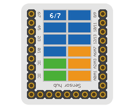
| − | *Referring to the following | + | *Referring to the following diagram, connect the Sensor-Color LED to the digital port D6 of '''[[Microduino-Sensorhub]]'''. |
<br> | <br> | ||
[[file:Microduino-sensorhub_Shake.JPG|thumb|400px|left]] | [[file:Microduino-sensorhub_Shake.JPG|thumb|400px|left]] | ||
<br style="clear: left"/> | <br style="clear: left"/> | ||
| − | === | + | ===Results=== |
| − | *After | + | *After download, open the serial monitor. |
| − | *LED | + | *LED flashes in red and green successively with the interval of 1s. |
==Application== | ==Application== | ||
| − | *LED full color | + | *LED full color light source |
| − | |||
==Project== | ==Project== | ||
| Line 79: | Line 84: | ||
* '''[[Applause Enthusiasm Detection]]''' | * '''[[Applause Enthusiasm Detection]]''' | ||
* '''[[Colored LED]]''' | * '''[[Colored LED]]''' | ||
| − | |||
| − | |||
| − | |||
==History== | ==History== | ||
Revision as of 06:05, 18 September 2016
| Language: | English • 中文 |
|---|
|
The product number of Sensor-Color LED is: MSDL11 Sensor-Color LED is full color LED, adopting single serial cascade protocol. Only one I/O port can control the RGB color of each LED on the line. If the power supply supports, it can support the cascade of as many as 1024 LEDs.
Contents[hide]Introduction of Sensor Pin
Features
Specification
Documents
DevelopmentProgram Download
Programming
Hardware Setup
Results
Application
ProjectHistoryGallery
|


