Difference between revisions of "Sensor-Color LED"
From Microduino Wiki
(→Specification) |
(→Documents) |
||
| Line 48: | Line 48: | ||
==Documents== | ==Documents== | ||
| − | *Schematic diagram: '''[[File: | + | *Schematic diagram: '''[[File: Sensor-Color_LED.Zip]]''' |
*Main chip: '''[[File: WS2812.pdf]]''' | *Main chip: '''[[File: WS2812.pdf]]''' | ||
*You can use the sample programs in the following IDE libraries to do experiment on your own: [https://github.com/wasdpkj/Microduino-IDE-Support/tree/master/arduino-ide-Support/%5B1.6.x%5D-hardware(library)/hardware/Microduino/avr/libraries '''_07_Sensor_LED_WS2812'''] | *You can use the sample programs in the following IDE libraries to do experiment on your own: [https://github.com/wasdpkj/Microduino-IDE-Support/tree/master/arduino-ide-Support/%5B1.6.x%5D-hardware(library)/hardware/Microduino/avr/libraries '''_07_Sensor_LED_WS2812'''] | ||
Revision as of 07:24, 8 November 2016
| Language: | English • 中文 |
|---|
|
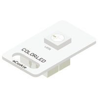
The product number of Sensor-Color LED is: MSDL11 Sensor-Color LED is full color LED, adopting single serial cascade protocol. Only one I/O port can control the RGB color of each LED on the line. If the power supply supports, it can support the cascade of as many as 1024 LEDs.
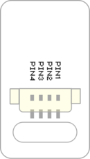
Contents[hide]Introduction of Sensor Pin
Features
Specification
Documents
DevelopmentProgram Download
Programming
Hardware Setup
Results
Application
ProjectHistoryGallery
|


