Difference between revisions of "Open Source Music Player"
From Microduino Wiki
(→Programming) |
|||
| (7 intermediate revisions by 3 users not shown) | |||
| Line 3: | Line 3: | ||
| | | | ||
==Overview== | ==Overview== | ||
| − | *Project | + | *Project name: Microduino open source player |
| − | * | + | *Objective: To read the songs in the SD card. |
*Difficulty: Medium | *Difficulty: Medium | ||
*Time consuming: 2 hours | *Time consuming: 2 hours | ||
| − | * | + | *Maker: |
*Introduction: | *Introduction: | ||
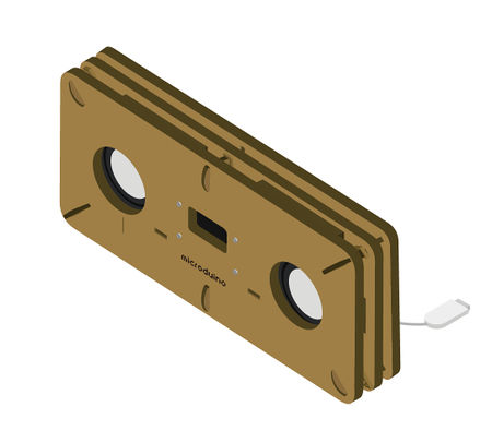
**Open source music player is an open source speaker which can read SD card and decode it. | **Open source music player is an open source speaker which can read SD card and decode it. | ||
| Line 18: | Line 18: | ||
|- | |- | ||
|width="50%" valign="top" align="left"| | |width="50%" valign="top" align="left"| | ||
| − | ===Microduino | + | ===Microduino equipment=== |
{|class="wikitable" | {|class="wikitable" | ||
|- | |- | ||
| Line 36: | Line 36: | ||
|} | |} | ||
|width="50%" valign="top" align="left"| | |width="50%" valign="top" align="left"| | ||
| − | ===Other | + | ===Other equipment=== |
{|class="wikitable" | {|class="wikitable" | ||
|- | |- | ||
| Line 45: | Line 45: | ||
|OLED connecting line||1||Connect | |OLED connecting line||1||Connect | ||
|- | |- | ||
| − | |Micro-USB line ||1||Download | + | |Micro-USB line ||1||Download programs, supply power |
|- | |- | ||
|Speaker||2||Play audio | |Speaker||2||Play audio | ||
| Line 67: | Line 67: | ||
==Programs to download== | ==Programs to download== | ||
| − | *The code of music player Github:'''[https://github.com/Microduino/ | + | *The code of music player Github:'''[https://github.com/Microduino/SimplePlayer_Microduino SimplePlayer_Microduino]''' |
==Programming== | ==Programming== | ||
*Stack '''[[Microduino-Core]]''' and '''[[Microduino-USBTTL]]''' together. | *Stack '''[[Microduino-Core]]''' and '''[[Microduino-USBTTL]]''' together. | ||
** Connect the '''[[Microduino-USBTTL]]''' ready to upload program with a data line. | ** Connect the '''[[Microduino-USBTTL]]''' ready to upload program with a data line. | ||
| − | ** | + | **Note: It is best not to put all modules stacked together and then upload. |
| − | *Open Arduino IDE for Microduino, environment, (Reference of the set- | + | *Open Arduino IDE for Microduino, environment, (Reference of the set-up: '''[[AVR Core: Getting Started]]'''). |
*Click'''[Instrument]''', assure the '''board card(Microduino-Core) processor(Atmega328P@16M,5V)''' selected correctly, and select the corresponding '''port number(COMX)'''. | *Click'''[Instrument]''', assure the '''board card(Microduino-Core) processor(Atmega328P@16M,5V)''' selected correctly, and select the corresponding '''port number(COMX)'''. | ||
*Click'''[File]'''->'''[Open]''', browse to the project program address, and click "'''Simple_player_V2.ino"''' to open program. | *Click'''[File]'''->'''[Open]''', browse to the project program address, and click "'''Simple_player_V2.ino"''' to open program. | ||
| Line 80: | Line 80: | ||
==Store audio== | ==Store audio== | ||
*Audio files need to be stored in a container in advance, then the player can play on them. There are two types of storage: | *Audio files need to be stored in a container in advance, then the player can play on them. There are two types of storage: | ||
| − | **The module board | + | **The module board FLASH: '''[[Microduino-Audio]]''' has boarded the 4MByte FLASH. |
***Audio storage method please refer to the following page: '''[https://www.microduino.cn/wiki/index.php/Microduino-Module_Audio #.E5.BC.80.E5.8F.91 Download audio]''' | ***Audio storage method please refer to the following page: '''[https://www.microduino.cn/wiki/index.php/Microduino-Module_Audio #.E5.BC.80.E5.8F.91 Download audio]''' | ||
**SD outside enlarge capacity: Use the '''Shield''' module of the '''[[Microduino-Audio]]''' module to realize '''MicroSD card dilatation'''. | **SD outside enlarge capacity: Use the '''Shield''' module of the '''[[Microduino-Audio]]''' module to realize '''MicroSD card dilatation'''. | ||
| Line 89: | Line 89: | ||
|- | |- | ||
|width="50%" valign="top" align="left"| | |width="50%" valign="top" align="left"| | ||
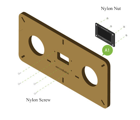
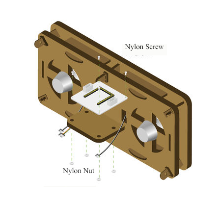
| − | *''' | + | *'''Step1: ''' |
*According to the picture 1-1, fix '''[[Microduino-OLED]]''' on '''Structure-A1''' with '''nylon screw''' and '''nylon nut''' . | *According to the picture 1-1, fix '''[[Microduino-OLED]]''' on '''Structure-A1''' with '''nylon screw''' and '''nylon nut''' . | ||
*Note: Pay attention to the installation direction of the OLED display screen, and please take the LOGO '''Microduino''' as a reference, the LOGO located in the '''positive direction''' saying it installed in the right direction. | *Note: Pay attention to the installation direction of the OLED display screen, and please take the LOGO '''Microduino''' as a reference, the LOGO located in the '''positive direction''' saying it installed in the right direction. | ||
| Line 98: | Line 98: | ||
|- | |- | ||
|width="50%" valign="top" align="left"| | |width="50%" valign="top" align="left"| | ||
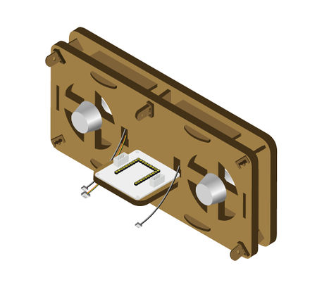
| − | *After the installation of the OLED display screen, please put | + | *After the installation of the OLED display screen, please put the sensor line access to the interface on the reverse of the OLED. |
|width="50%" valign="top" align="left"| | |width="50%" valign="top" align="left"| | ||
[[File:Musicstep1-2.jpg||450px|center]] | [[File:Musicstep1-2.jpg||450px|center]] | ||
| Line 105: | Line 105: | ||
|- | |- | ||
|width="50%" valign="top" align="left"| | |width="50%" valign="top" align="left"| | ||
| − | *''' | + | *'''Step2:''' |
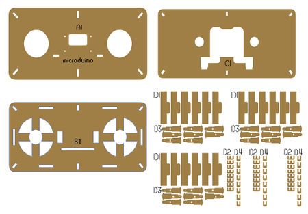
*According to the picture 2-1, insert '''structure-D1''' into the corresponding interface of the '''structure-B1'''. | *According to the picture 2-1, insert '''structure-D1''' into the corresponding interface of the '''structure-B1'''. | ||
|width="50%" valign="top" align="left"| | |width="50%" valign="top" align="left"| | ||
| Line 127: | Line 127: | ||
|- | |- | ||
|width="50%" valign="top" align="left"| | |width="50%" valign="top" align="left"| | ||
| − | *''' | + | *'''Step3:''' |
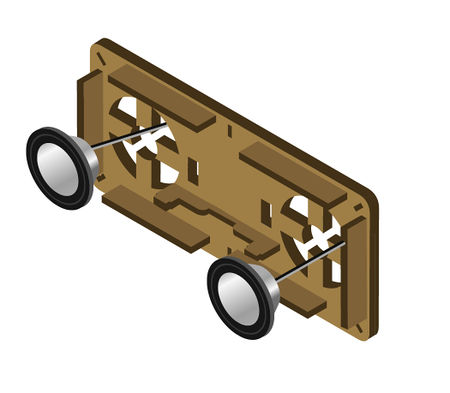
*According to the picture 3-1, embed the '''horn''' into the position as shown in the picture, taking care of the installation direction of the '''horn''', the '''horn line''' needing threading to the behind of the '''structure-B1''' in advance. | *According to the picture 3-1, embed the '''horn''' into the position as shown in the picture, taking care of the installation direction of the '''horn''', the '''horn line''' needing threading to the behind of the '''structure-B1''' in advance. | ||
|width="50%" valign="top" align="left"| | |width="50%" valign="top" align="left"| | ||
| Line 149: | Line 149: | ||
|- | |- | ||
|width="50%" valign="top" align="left"| | |width="50%" valign="top" align="left"| | ||
| − | *''' | + | *'''Step4:''' |
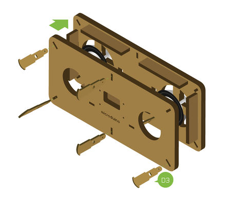
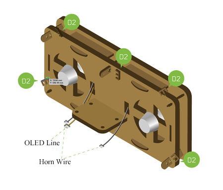
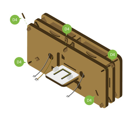
*According to the picture 4-1, turn to the back of the player, stuck '''structure-D2''' with the slot of '''structure-D3'''. | *According to the picture 4-1, turn to the back of the player, stuck '''structure-D2''' with the slot of '''structure-D3'''. | ||
** Pay attention to the force evenly, avoid too much force to break, and at the same time thread the two '''horn''' line and OLED line out from the hole on the back. | ** Pay attention to the force evenly, avoid too much force to break, and at the same time thread the two '''horn''' line and OLED line out from the hole on the back. | ||
| Line 173: | Line 173: | ||
|- | |- | ||
|width="50%" valign="top" align="left"| | |width="50%" valign="top" align="left"| | ||
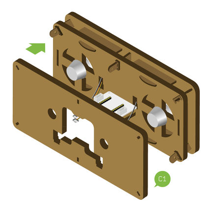
| − | *''' | + | *'''Step5:''' |
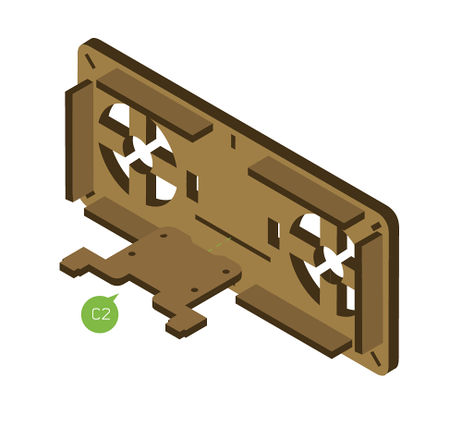
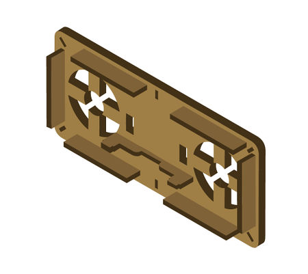
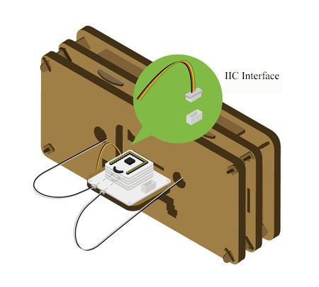
*According to the picture 5-1, insert '''structure-C1''' into the back of the player. | *According to the picture 5-1, insert '''structure-C1''' into the back of the player. | ||
|width="50%" valign="top" align="left"| | |width="50%" valign="top" align="left"| | ||
| Line 198: | Line 198: | ||
|- | |- | ||
|width="50%" valign="top" align="left"| | |width="50%" valign="top" align="left"| | ||
| − | *''' | + | *'''Step6:''' |
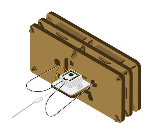
*According to the picture 6-1, connect the OLED line to the IIC interface(There are SCL,SDA near the interface)on the left of the baseboard of the '''[[Microduino-Cube-S1]]'''. | *According to the picture 6-1, connect the OLED line to the IIC interface(There are SCL,SDA near the interface)on the left of the baseboard of the '''[[Microduino-Cube-S1]]'''. | ||
*Then connect the two '''horn''' lines to the audio interface in the '''[[Microduino-Amplifier]]'''module. | *Then connect the two '''horn''' lines to the audio interface in the '''[[Microduino-Amplifier]]'''module. | ||
| Line 243: | Line 243: | ||
*The following code can set the thumbwheel switch threshold | *The following code can set the thumbwheel switch threshold | ||
<source lang = "cpp"> | <source lang = "cpp"> | ||
| − | #define PUSH_BUTTON 50 | + | #define PUSH_BUTTON 50 //If the threshold value is invalid, please try these thresholds 50 |
| − | #define LEFT_BUTTON 100 | + | #define LEFT_BUTTON 100 150 |
| − | #define RIGHT_BUTTON 200 | + | #define RIGHT_BUTTON 200 250 |
</source> | </source> | ||
| − | *In the event | + | *In the event of: The volume can only be increased and can't be reduced, the number of the song can only be increased and can't be reduced, or on the contrary. |
Cause:The thumbwheel switches threshold setting is not reasonable in the "userDef.h". | Cause:The thumbwheel switches threshold setting is not reasonable in the "userDef.h". | ||
{|class="wikitable" | {|class="wikitable" | ||
Latest revision as of 06:19, 30 September 2016
ContentsOverview
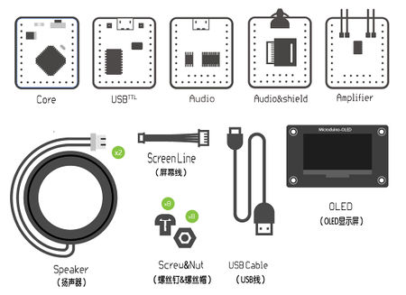
Bill of materials
Programs to download
Programming
Store audio
Steps of the set-up
Operating instructionPlayer power supply
Players use
Code instruction
#define PUSH_BUTTON    50             //If the threshold value is invalid, please try these thresholds   50
#define LEFT_BUTTON    100                                                                               150
#define RIGHT_BUTTON   200                                                                               250
Cause:The thumbwheel switches threshold setting is not reasonable in the "userDef.h".
Please change the threshold in the "userDef.h" to the actual using value of the thumbwheel. Video |
