Difference between revisions of "Lesson 3--Microduino "Button Controlled LED""
From Microduino Wiki
m (Changliu818@yahoo.com moved page Lesson 3--Button switch control LED to Lesson 3--Microduino "Button Controlled LED") |
|||
| Line 4: | Line 4: | ||
| | | | ||
==Objective== | ==Objective== | ||
| − | The first two | + | The first two lessons showed you how to use software to control the LED directly. If we add a button |
| − | to control the LED light, then | + | to control the LED light, then we can combine the use of both hardware and software. |
| − | + | Previously, we used Microduino I/O port as the output to control the LED. So if want to use a button, | |
| − | how | + | how would we monitor the input signal of the button? |
| − | + | In this lesson, we will use a button as an example to show how to use Microduino as the input. | |
| Line 15: | Line 15: | ||
*'''[[Microduino-FT232R]]''' | *'''[[Microduino-FT232R]]''' | ||
*Other hardware equipment | *Other hardware equipment | ||
| − | ** | + | **1x Box of breadboard jumper wires |
| − | **Breadboard | + | **1x Breadboard |
| − | **LED Light- | + | **1x LED (Light-Emitting Diode) |
| − | **220ohm resistor | + | **1x 220ohm resistor |
| − | **Button | + | **1x Button |
| − | **USB Data cable | + | **1x USB Data cable |
==Button== | ==Button== | ||
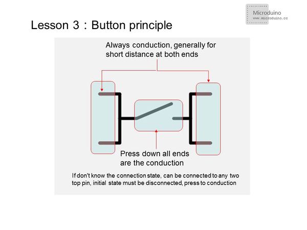
*Button principle | *Button principle | ||
[[File:button.jpg|600px|center|thumb]] | [[File:button.jpg|600px|center|thumb]] | ||
| − | |||
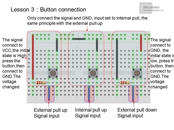
*Button connection | *Button connection | ||
| Line 32: | Line 31: | ||
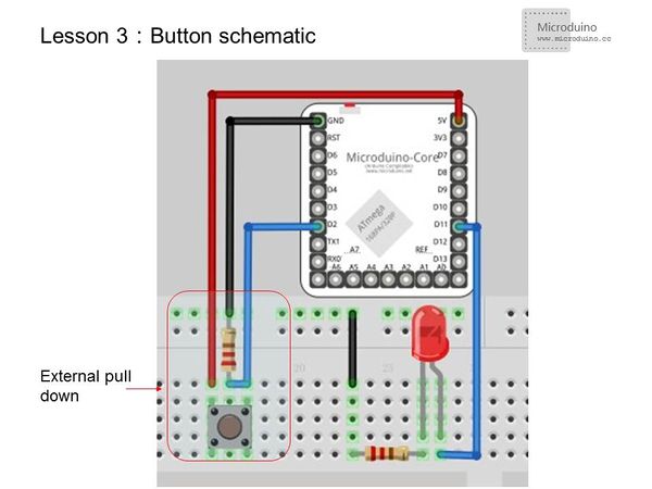
==Experimental schematic== | ==Experimental schematic== | ||
[[File:button schematic.jpg|600px|center|thumb]] | [[File:button schematic.jpg|600px|center|thumb]] | ||
| − | Using external pulldown | + | Using external pulldown method, when unpressed, it is "LOW". When pressed, it is high. |
| Line 44: | Line 43: | ||
void setup() { | void setup() { | ||
pinMode(ledPin, OUTPUT); //Set the LED pin as output | pinMode(ledPin, OUTPUT); //Set the LED pin as output | ||
| − | pinMode(buttonPin, INPUT); //Set button pin as | + | pinMode(buttonPin, INPUT); //Set button pin as input |
} | } | ||
void loop(){ | void loop(){ | ||
buttonState = digitalRead(buttonPin);//Read the value from the buttonPin | buttonState = digitalRead(buttonPin);//Read the value from the buttonPin | ||
if (buttonState == HIGH) { | if (buttonState == HIGH) { | ||
| − | digitalWrite(ledPin, HIGH); //If the button input signal is high, the LED will light | + | digitalWrite(ledPin, HIGH); //If the button input signal is high, the LED will light up |
} | } | ||
else { | else { | ||
| Line 67: | Line 66: | ||
pinMode(ledPin, OUTPUT); | pinMode(ledPin, OUTPUT); | ||
// pinMode(buttonPin, INPUT); //Set the button pin as input | // pinMode(buttonPin, INPUT); //Set the button pin as input | ||
| − | pinMode(buttonPin, INPUT_PULLUP);//Set button pin as | + | pinMode(buttonPin, INPUT_PULLUP);//Set button pin as internal pull-up input |
} | } | ||
void loop(){ | void loop(){ | ||
buttonState = digitalRead(buttonPin); | buttonState = digitalRead(buttonPin); | ||
| − | if (buttonState ==HIGH) | + | if (buttonState ==HIGH) |
{ | { | ||
| − | delay(200); | + | delay(200); //Short time delay for stabilization |
// delay(1000); //Long time press | // delay(1000); //Long time press | ||
| − | // if (buttonState == LOW) | + | // if (buttonState == LOW) //Check still is low |
| − | led=!led; | + | led=!led; //LED state flip |
} | } | ||
digitalWrite(ledPin, led); | digitalWrite(ledPin, led); | ||
} | } | ||
</source> | </source> | ||
| − | + | ||
| − | + | ===digitalRead()usage=== | |
| − | + | Read a pin's value and return HIGH or LOW. | |
| − | === | ||
| − | Read a | ||
==Result== | ==Result== | ||
| − | *Program 1:LED display input button value. High value will light | + | *Program 1:LED display input button value. High value will light the LED. |
| − | *Program 2:Each time you press the button, | + | *Program 2:Each time you press the button, LED voltage will flip. |
==Video== | ==Video== | ||
|} | |} | ||
Revision as of 11:46, 12 July 2015
| Language: | English • 中文 |
|---|
ContentsObjectiveThe first two lessons showed you how to use software to control the LED directly. If we add a button to control the LED light, then we can combine the use of both hardware and software. Previously, we used Microduino I/O port as the output to control the LED. So if want to use a button, how would we monitor the input signal of the button? In this lesson, we will use a button as an example to show how to use Microduino as the input.
Equipment
Button
Experimental schematicUsing external pulldown method, when unpressed, it is "LOW". When pressed, it is high.
Program
const int buttonPin = 2;     // Define button input pin
const int ledPin =  11;     //Define LED pin
int buttonState = 0;        //Initialize the button value
void setup() {
  pinMode(ledPin, OUTPUT);    //Set the LED pin as output
  pinMode(buttonPin, INPUT);  //Set button pin as input
}
void loop(){
  buttonState = digitalRead(buttonPin);//Read the value from the buttonPin
  if (buttonState == HIGH) {
    digitalWrite(ledPin, HIGH); //If the button input signal is high, the LED will light up
  }
  else {
    digitalWrite(ledPin, LOW); //LED goes out
  }
}
const int buttonPin = 2;     // Define button input pin
const int ledPin =  11;

int buttonState = 0;
boolean led;         //Define LED as boolean(true or false)
void setup() {
  pinMode(ledPin, OUTPUT);
  // pinMode(buttonPin, INPUT); //Set the button pin as input
  pinMode(buttonPin, INPUT_PULLUP);//Set button pin as internal pull-up input
}
void loop(){
  buttonState = digitalRead(buttonPin);
  if (buttonState ==HIGH)
  {
    delay(200);                   //Short time delay for stabilization
    // delay(1000);               //Long time press
    // if (buttonState == LOW)    //Check still is low
    led=!led;                     //LED state flip
  }
  digitalWrite(ledPin, led);
}digitalRead()usageRead a pin's value and return HIGH or LOW. Result
Video |


