Difference between revisions of "Lesson 8--Microduino "Pulse Recorder""
(Created page with "{| style="width: 800px;" |- | ==Objective== Lesson showed how to use the button and aviod shaking issue. The solution is add a delay. But this solution has a disadvantage. De...") |
|||
| Line 23: | Line 23: | ||
==Experimental schematic== | ==Experimental schematic== | ||
| − | [[File: | + | [[File:lesson8-schematic.jpg|600px|center|thumb]] |
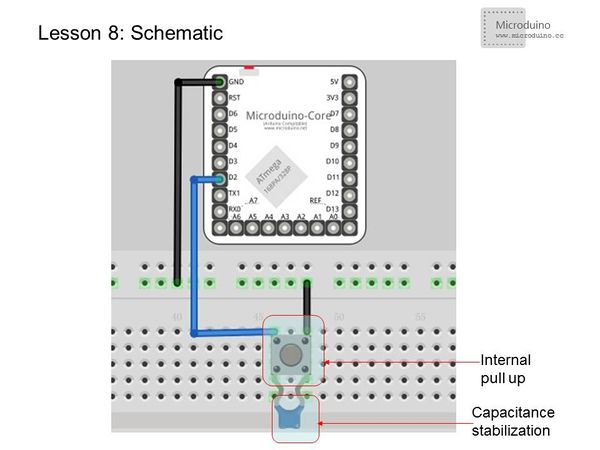
Using the internal pull-up, external 104 ceramic capacitors for stabilization. | Using the internal pull-up, external 104 ceramic capacitors for stabilization. | ||
| Line 52: | Line 52: | ||
===Open the serial port monitor=== | ===Open the serial port monitor=== | ||
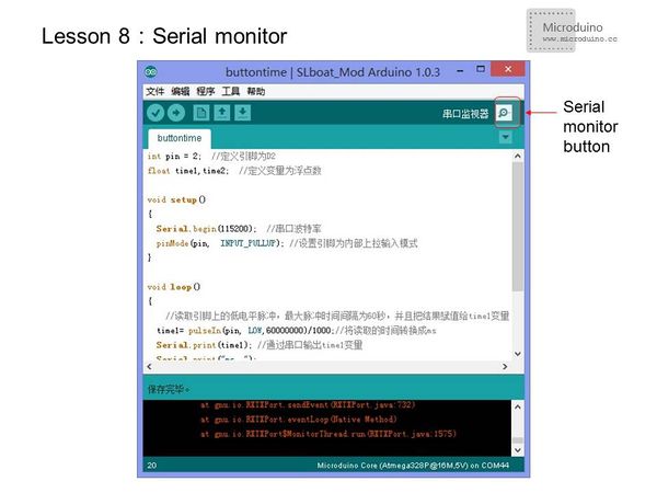
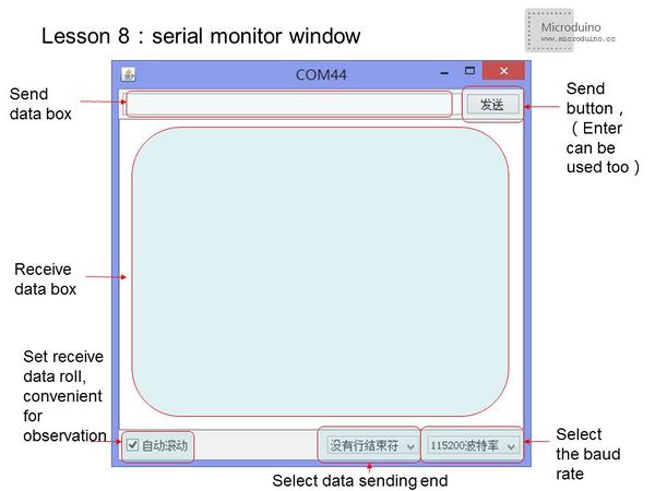
*Click the Serial Monitor button, pop-up the serial monitor interface. | *Click the Serial Monitor button, pop-up the serial monitor interface. | ||
| − | [[File: | + | [[File:lesson8-serialmonitor.jpg|600px|center|thumb]] |
| − | [[File: | + | [[File:lesson8-serialwindow.jpg|600px|center|thumb]] |
*Note: | *Note: | ||
| Line 60: | Line 60: | ||
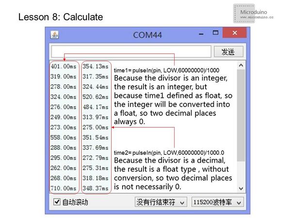
*When convert the unit, need pat attention to the data type: | *When convert the unit, need pat attention to the data type: | ||
| − | [[File: | + | [[File:lesson-calculate.jpg|600px|center|thumb]] |
===PulseIn()function=== | ===PulseIn()function=== | ||
| Line 75: | Line 75: | ||
==Result== | ==Result== | ||
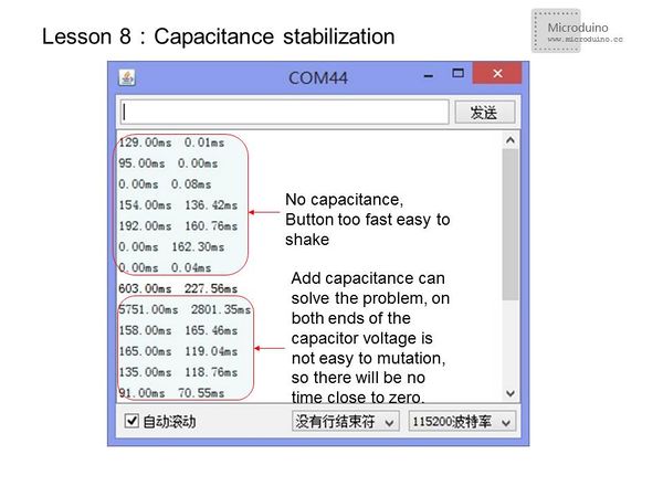
For stabilization,add a 104 ceramic capacitors in signal change port, you can see a better result. | For stabilization,add a 104 ceramic capacitors in signal change port, you can see a better result. | ||
| − | [[File: | + | [[File:lesson8-capacitance.jpg|600px|center|thumb]] |
==Video== | ==Video== | ||
|} | |} | ||
Revision as of 08:10, 16 February 2014
ContentsObjectiveLesson showed how to use the button and aviod shaking issue. The solution is add a delay. But this solution has a disadvantage. Delay time according to the specific situation, because everyone is different to press the button. This lesson will introduce how to get the time to press a button, the program uses a pulse timing calculation. Besides that, you can learn how to use arduino's serial and monitor the data using serial. Equipment
PulsePulse is a process that a physical quantity quickly retun to its initial state after a short time mutation. In Microduino, pulse just a digital signal which changed between high and low in cyclical. Pulse timing is often used in the photoelectric encoder, Hall elements to calculate the speed. Experimental schematicUsing the internal pull-up, external 104 ceramic capacitors for stabilization. Programint pin = 2; //Define Pin D2
float time1,time2; //Define variables to float
void setup()
{
Serial.begin(115200); //Serial port baud rate
pinMode(pin, INPUT_PULLUP); //Set pin to input mode with the internal pull-up
}
void loop()
{
//Read low pulse from the pin, the maximum pulse interval is 60 seconds, and assign the result to the variable time1
time1= pulseIn(pin, LOW,60000000)/1000;//Convert the time to ms
Serial.print(time1); //Output the time1 by serial
Serial.print("ms ");
time2= pulseIn(pin, LOW,60000000)/1000.0;//Convert the time to ms
Serial.print(time2); //Output the time1 by serial
Serial.println("ms");//Through the serial port to print out the unit and wrap to a new line to output the next value.
}
}Serial monitoringOpen the serial port monitor
PulseIn()function
The return value is the pulse time, unit is us. The timer range is 10us ~ 3mins. (1s=1000ms=1000000us)
ResultFor stabilization,add a 104 ceramic capacitors in signal change port, you can see a better result. Video |
