Difference between revisions of "Microduino-Module WIFI,ESP"
(→Application) |
|||
| (13 intermediate revisions by 3 users not shown) | |||
| Line 4: | Line 4: | ||
| | | | ||
[[file:Microduino-8266-rect.jpg|400px|thumb|right|Microduino-ESP]] | [[file:Microduino-8266-rect.jpg|400px|thumb|right|Microduino-ESP]] | ||
| − | Microduino-WIFI(ESP) is a WIFI communication module, which can communicate with | + | Microduino-WIFI(ESP) is a WIFI communication module, which can communicate with Core+/CoreUSB (Core can not be used, because its baud rate can't reach at 115200.) through the serial port or connect with other WIFI devices and is a complete and system-in-itself wifi network resolution. |
==Features== | ==Features== | ||
*Serial communication. | *Serial communication. | ||
*Internet connection available. | *Internet connection available. | ||
| − | *Small, cheap, | + | *Small, cheap, stack-able and open. |
*High on-chip integration. | *High on-chip integration. | ||
*Have a strong on-chip processing and storage capabilities. | *Have a strong on-chip processing and storage capabilities. | ||
*Reduce the occupancy of system resources in operation. | *Reduce the occupancy of system resources in operation. | ||
| − | *Available for integrating | + | *Available for integrating sensor and other application specific devices through the GPIO port. |
==Specification== | ==Specification== | ||
| − | *Communication method: Serial | + | *Communication method: Serial pass through with the default serial port D2(RX), D3(TX); |
| − | *Power supply: +3.3VDC | + | *Power supply: +3.3VDC 50mA; |
| − | *Status indicator | + | *Status indicator; |
| − | *SDIO 2.0, SPI and UART interface | + | *SDIO 2.0, SPI and UART interface; |
| − | *32-pin QFN sealed | + | *32-pin QFN sealed ; |
| − | *With RF switch, balun, LNA, 24 PA dBm, DCXO and power management unit (PMU) integrated | + | *With RF switch, balun, LNA, 24 PA dBm, DCXO and power management unit (PMU) integrated; |
| − | *With RISC processor, on-chip memory and external memory interface integrated | + | *With RISC processor, on-chip memory and external memory interface integrated; |
| − | *With MAC/ baseband processor integrated | + | *With MAC/ baseband processor integrated; |
| − | *High quality service management | + | *High quality service management; |
| − | *With I2S interface required by high fidelity audio applications | + | *With I2S interface required by high fidelity audio applications; |
| − | *All internal power supply contains on-chip low dropout linear regulator | + | *All internal power supply contains on-chip low dropout linear regulator; |
| − | *Proprietary spurious free clock generation architecture | + | *Proprietary spurious free clock generation architecture; |
| − | *With WEP, TKIP, AES, and WAPI engines integrated | + | *With WEP, TKIP, AES, and WAPI engines integrated. |
| − | + | ||
==Common AT Instruction== | ==Common AT Instruction== | ||
| − | *All AT instructions are ended with "\r\n ". When debugging the AT commands, please pay attention to the choice of | + | *All AT instructions are ended with "\r\n ". When debugging the AT commands, please pay attention to the choice of "\r\n". |
*Common AT instruction: | *Common AT instruction: | ||
| − | **AT+RST Restart the module | + | **AT+RST Restart the module; |
| − | **AT+GMR Check the version information | + | **AT+GMR Check the version information; |
| − | **AT+CWMODE=3 Station and access point | + | **AT+CWMODE=3 Station and access point; |
| − | ***1 Station Mode | + | ***1 Station Mode; |
| − | ***2 AP Mode | + | ***2 AP Mode; |
| − | ***3 AP and the Station | + | ***3 AP and the Station. |
| − | + | **AT+CWLAP WIFI SSID List; | |
| − | **AT+CWLAP WIFI SSID List | + | **AT+CWSMARTSTART=0 Start smart connection: |
| − | + | ***0: Adopt AL-LINK technology; | |
| − | **AT+CWSMARTSTART=0 Start smart connection | + | ***1: Adopt ESP-TOUCH; |
| − | ***0: Adopt AL-LINK technology | + | ***2: Adopt AIR-KISS. |
| − | ***1: Adopt ESP-TOUCH | + | **AT+CWSMARTSTOP Stop the smart connection; |
| − | ***2: Adopt AIR-KISS | + | **AT+CWJAP="<access_point_name>","<password>" Join in a certain WIFI; |
| − | + | **AT+CIFSR Display the information of wifi; | |
| − | **AT+CWSMARTSTOP Stop the smart connection | + | **AT+CIPSTATUS Acquire the connection status; |
| − | + | **AT+CIPSTART=4,"TCP","baidu.com",80 Establish TCP/UDP connection and ports; | |
| − | **AT+CWJAP="<access_point_name>","<password>" Join in a certain WIFI | + | **AT+CIPCLOSE Close the connection of TCP/UDP(single connection); |
| − | + | **AT+CIPCLOSE=5 Close multiple connections; | |
| − | **AT+CIFSR Display the information of wifi | ||
| − | |||
| − | **AT+CIPSTATUS Acquire the connection status | ||
| − | |||
| − | **AT+CIPSTART=4,"TCP","baidu.com",80 Establish TCP/UDP connection and ports | ||
| − | |||
| − | **AT+CIPCLOSE Close the connection of TCP/UDP(single connection) | ||
| − | |||
| − | **AT+CIPCLOSE=5 Close multiple connections | ||
| − | |||
**AT+CIPMUX=1 Start multiple connections. | **AT+CIPMUX=1 Start multiple connections. | ||
| Line 88: | Line 78: | ||
the program, after the end of the compilation click -> button is programmed to the board; | the program, after the end of the compilation click -> button is programmed to the board; | ||
| − | *Open the serial monitor, | + | *Open the serial monitor, set:"\r\n", "115200 baud". |
*First of prompts is to show connect WiFi successful information | *First of prompts is to show connect WiFi successful information | ||
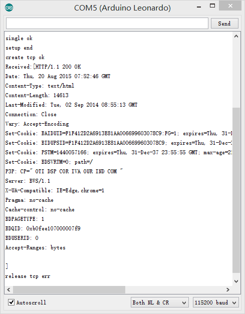
*If you see the following description you already visited Baidu Home website. | *If you see the following description you already visited Baidu Home website. | ||
| Line 107: | Line 97: | ||
**[[Open Source Smart Socket]] | **[[Open Source Smart Socket]] | ||
| − | ==Firmware | + | ==Firmware Programming== |
| − | + | ===Download the Programming Tool=== | |
| − | + | *Programming tool:'''[[File:ESP8266Flasher.rar]]''' | |
| + | *Firmware:'''[[File:MicroduinoESP8266.rar]]''' | ||
| + | |||
| + | You can use English Flasher see http://www.xess.com/blog/esp8266-reflash/ with Firmware MicroduinoESP8266 binary | ||
| − | + | ===Modules Connection=== | |
| − | + | *Before programming, you need to prepare the serial port environment of the WIFI module. | |
| + | *The serial port the WIFI module uses is serial port 1(D2, D3), so there are two methods of connect: | ||
| + | *Method A: Use USBTTL to transform through the serial port. | ||
| + | **For cables are needed to connect the serial ports together. | ||
{| class="wikitable" | {| class="wikitable" | ||
|- | |- | ||
| Line 125: | Line 121: | ||
| GND || GND | | GND || GND | ||
|} | |} | ||
| − | + | ||
| − | Core+ | + | *Method B: Use core to cooperate to program firmware. |
| − | baud rate | + | **Stack USBTTL, Core+ and WIFI together(Core can not be used, because its baud rate can't reach at 115200.) |
| − | + | **Download the following program to Core+ | |
<source lang="cpp"> | <source lang="cpp"> | ||
| − | |||
| − | |||
void setup() { | void setup() { | ||
Serial.begin(115200); | Serial.begin(115200); | ||
| − | + | Serial1.begin(115200); | |
} | } | ||
| Line 140: | Line 134: | ||
if (Serial.available()) { | if (Serial.available()) { | ||
char c = Serial.read(); | char c = Serial.read(); | ||
| − | + | Serial1.write(c); | |
| − | } if ( | + | } if (Serial1.available()) { |
| − | char c = | + | char c = Serial1.read(); |
Serial.write(c); | Serial.write(c); | ||
} | } | ||
} | } | ||
</source> | </source> | ||
| − | |||
| − | |||
| − | |||
| − | |||
| − | |||
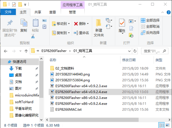
| − | + | ===Configure Programming Tool=== | |
| + | *Open the programming tool, and set the firmware and parameters according to the graphic. | ||
| + | [[File:Microuino-WiFi(ESP)burnSoftwareDir.png|thumb|600px|center]] | ||
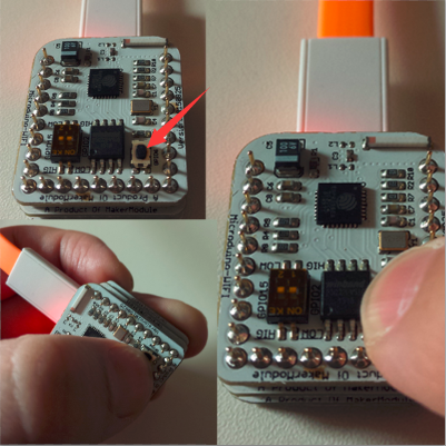
| − | + | ===Programming=== | |
| − | [[File:Microuino-WiFi(ESP) | + | *Press the GPIO0 key of WIFI module, and connect to USB to power. |
| + | *The choose the corresponding serial port, and click START key to download the program. | ||
| + | [[File:Microuino-WiFi(ESP)burnLoarderButton1.png|thumb|600px|center]] | ||
| − | + | ===Function Verification=== | |
| + | *3: After downloading, powered again, it can work normally. | ||
| + | *Open the serial port debugging tool, and test the AT command to confirm whether the downloading is successful or not. | ||
| − | + | ==FAQ== | |
| − | + | ==Players Community== | |
| − | |||
| − | |||
| − | |||
| − | |||
| − | |||
| − | |||
| − | + | At present, there are many playing methods of ESP8266, and according to the different kinds of the firmware, they can be roughly divided into: | |
| − | + | *1. AT firmware method is using Arduino mcu combining with ESP8266 brushed with the AT command to implement the internet of things; | |
| − | + | *2. NodeMCU firmware method refers to brush ESP8266 firmware to NodeMCU, then use Arduino IDE for ESP8266 to compile program and brush to the corresponding flash zone to implement the control. Besides, this firmware can also be compile program with NodeMcu Studio 2015 or LuaLoader, in LUA language , to implement the internet of things; | |
| + | *3. SDK method refers to use sdk provided by such as Lexin, Essence and Guoyun Techonology to build project, which combines with eclipse and cygwin to generate the firmware programming. And the language this method adopts are c and c++. At present, GizWits, HEKR and tisan in our country are all implemented by this method. | ||
| + | *4. Micropython method is similar to the front one. Use Micropython SDK to compile and program firmware, and then use putty or other serial port software to run the program on the basis of python language. | ||
| − | == | + | From:http://www.geek-workshop.com/forum.php?mod=viewthread&tid=25456&page=1&extra=#pid114413 |
==Gallery== | ==Gallery== | ||
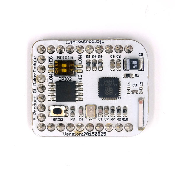
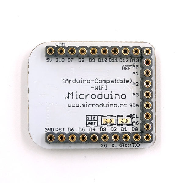
| − | [[file: | + | [[file:8266back.jpg|thumb|600px|center]] |
| − | [[file: | + | [[file:8266front.jpg|thumb|600px|center]] |
|} | |} | ||
Latest revision as of 05:58, 4 August 2017
| Language: | English • 中文 |
|---|
|
Microduino-WIFI(ESP) is a WIFI communication module, which can communicate with Core+/CoreUSB (Core can not be used, because its baud rate can't reach at 115200.) through the serial port or connect with other WIFI devices and is a complete and system-in-itself wifi network resolution. ContentsFeatures
Specification
Common AT Instruction
Documents
Development
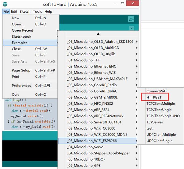
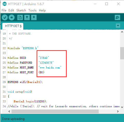
Use Microduino IDE-->example-->_03_microduino_WiFi_ESP8266-->HTTPGET program test is OK. You can change the WIFI password where you set the SSID (WIFI name) and the password in the code.
insert USB line into the Microduino-USBttl, other side of USB line insert into computer, start Arduino IDE, The above program is copied to the IDE, the tool (tools) -> Board (Board) is selected Microduino Core, and the tools (tools) -> Serial Port (Serial) select the corresponding serial number. After clicking the top left corner IDE √ button to compile the program, after the end of the compilation click -> button is programmed to the board;
Application
Firmware ProgrammingDownload the Programming Tool
You can use English Flasher see http://www.xess.com/blog/esp8266-reflash/ with Firmware MicroduinoESP8266 binary Modules Connection
void setup() {
  Serial.begin(115200);
  Serial1.begin(115200);
}

void loop() {
  if (Serial.available()) {
    char c = Serial.read();
    Serial1.write(c);
  } if (Serial1.available()) {
    char c = Serial1.read();
    Serial.write(c);
  }
}
Configure Programming Tool
Programming
Function Verification
FAQPlayers CommunityAt present, there are many playing methods of ESP8266, and according to the different kinds of the firmware, they can be roughly divided into:
From:http://www.geek-workshop.com/forum.php?mod=viewthread&tid=25456&page=1&extra=#pid114413 Gallery |

