Difference between revisions of "Microduino-Module Zigbee"
From Microduino Wiki
(→Projects) |
|||
| (7 intermediate revisions by 2 users not shown) | |||
| Line 14: | Line 14: | ||
*CC2530 combines high performance of the leading RF transceiver and the standard enhanced 8051 CPU in the industry, owning in-system programmable flash, 8-KB RAM and many other powerful functions. | *CC2530 combines high performance of the leading RF transceiver and the standard enhanced 8051 CPU in the industry, owning in-system programmable flash, 8-KB RAM and many other powerful functions. | ||
| − | *Serial | + | *Serial transmission; |
| − | *Reserved CCDEBUG interface, making it easier for | + | *Reserved CCDEBUG interface, making it easier for users' second development; |
*Enough power, easy to reach 100 meters wirelessly; | *Enough power, easy to reach 100 meters wirelessly; | ||
*Small, cheap, stackable and open source; | *Small, cheap, stackable and open source; | ||
*Open source hardware circuit design and Arduino compatible programming development environment; | *Open source hardware circuit design and Arduino compatible programming development environment; | ||
*Uniform Microduino interface standard makes it easy and flexible to connect and extend with other Microduino modules; | *Uniform Microduino interface standard makes it easy and flexible to connect and extend with other Microduino modules; | ||
| − | *2.54mm pin pitch makes it easy to be integrated to a pegboard. | + | *2.54mm pin pitch makes it easy to be integrated to a pegboard. |
==Specification== | ==Specification== | ||
Specification of electrical application | Specification of electrical application | ||
*RF/Layout | *RF/Layout | ||
| − | **RF transceiver suitable for 2.4-GHz IEEE 802.15.4 | + | **RF transceiver suitable for 2.4-GHz IEEE 802.15.4 ; |
| − | **Extremely high receiving sensitivity and resistance to interference | + | **Extremely high receiving sensitivity and resistance to interference ; |
| − | ** | + | **Programming output power is up to 4.5 dBm ; |
| − | **System configuration suitable Radio Frequency Regulations: ETSI EN 300 328 and EN 300440 (in Europe), Part 15 FCC CFR47 (in US.) and ARIB STD-T-66 (in Japan) | + | **System configuration suitable Radio Frequency Regulations: ETSI EN 300 328 and EN 300440 (in Europe), Part 15 FCC CFR47 (in US.) and ARIB STD-T-66 (in Japan). |
*Low Power Consumption | *Low Power Consumption | ||
| − | **Active Mode RX (CPU free): 24mA | + | **Active Mode RX (CPU free): 24mA; |
| − | **Active Mode TX in 1dBm (CPU free): 29mA | + | **Active Mode TX in 1dBm (CPU free): 29mA; |
| − | **Power Supply Mode 1 (4μs Awaking): 0.2mA | + | **Power Supply Mode 1 (4μs Awaking): 0.2mA; |
| − | ** Power Supply Mode 2 (Sleep Timer Running): μA | + | ** Power Supply Mode 2 (Sleep Timer Running): μA; |
| − | ** Power Supply Mode 3 (External Interrupt): 0.4 μA | + | ** Power Supply Mode 3 (External Interrupt): 0.4 μA; |
| − | **Wide supply voltage range (2 V–3.6 V) (2 V–3.6 V) | + | **Wide supply voltage range (2 V–3.6 V) (2 V–3.6 V). |
*Microcontroller | *Microcontroller | ||
| − | **Fine performance and low-power 8051 microcontroller core with code prefetching function | + | **Fine performance and low-power 8051 microcontroller core with code prefetching function; |
| − | **256KB in-system programmable flash | + | **256KB in-system programmable flash; |
| − | **8-KB RAM, capable of data saving in various power supply | + | **8-KB RAM, capable of data saving in various power supply mode; |
| − | **Support hardware debugging | + | **Support hardware debugging. |
*Peripherals | *Peripherals | ||
| − | **Strong 5-channel DMA | + | **Strong 5-channel DMA; |
| − | **IEEE 802.5.4 MAC timer and general purpose timer | + | **IEEE 802.5.4 MAC timer and general purpose timer(One is 16-bit and the other is 8-bit timer.) ; |
| − | **32-KHz sleep timer with capture function | + | **32-KHz sleep timer with capture function; |
| − | **Hardware support CSMA/CA | + | **Hardware support CSMA/CA; |
| − | **AES secure coprocessor | + | **AES secure coprocessor; |
| − | **WATCHDOG Timer | + | **WATCHDOG Timer. |
| − | *Pin | + | *Pin description: |
{|class="wikitable" | {|class="wikitable" | ||
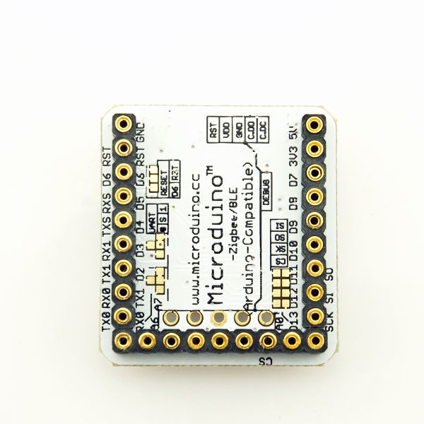
! rowspan="1" | Chip pin || Microduino pin || Function | ! rowspan="1" | Chip pin || Microduino pin || Function | ||
| Line 77: | Line 77: | ||
==Projects== | ==Projects== | ||
| − | |||
==Purchase== | ==Purchase== | ||
Latest revision as of 06:01, 4 August 2017
| Language: | English • 中文 |
|---|
|
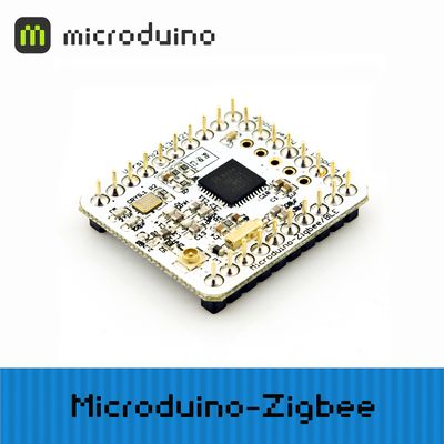
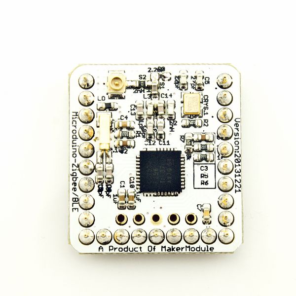
Microduino-Zigbee adopts CC2530 chip, which is a short-distance, simple, low-power, low-rate and low-cost bidirectional wireless communication technology. It is mainly used in data transmission applications among various electronic devices.
Contents[hide]Features
SpecificationSpecification of electrical application
DocumentAT command documentation:File:Zigbee AT en.pdf DevelopmentProjectsPurchaseHistoryPicturesFrontBackVideo |


