Difference between revisions of "Sensor-Servo Connector"
(→Application) |
|||
| (2 intermediate revisions by one other user not shown) | |||
| Line 10: | Line 10: | ||
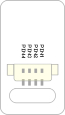
==Introduction of Pins== | ==Introduction of Pins== | ||
| − | {{ | + | {{ST_Pinout |
| − | | | + | |st_name=Servo Connector |
| − | | | + | |pin3=Digital Output (Servo Signal 1) |
| − | | | + | |pin4=Digital Output (Servo Signal 2) |
}} | }} | ||
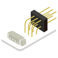
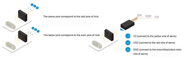
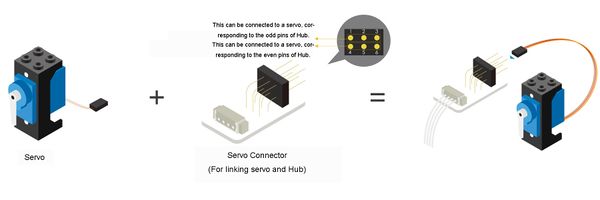
The servo can not link with the extension module (hub) directly, so a servo connector is needed. The servo connector have 3 above pins and 3 below pins, which can connect to two servos at the same time. | The servo can not link with the extension module (hub) directly, so a servo connector is needed. The servo connector have 3 above pins and 3 below pins, which can connect to two servos at the same time. | ||
[[File:anywhere_Servo-Servo Connector.jpg|600px|center]] | [[File:anywhere_Servo-Servo Connector.jpg|600px|center]] | ||
| − | When connecting the servo and the | + | When connecting the servo and the servo connector, please pay attention to the "positive and negative" , and make sure that the GND, VCC, and 1/2 three wires are connected rightly. The above pins is corresponding to the odd pins of Hub, and the below pins is corresponding to the event pins of Hub. For example, when connecting the servo to the 6/7 pin of Hub, if the servo is connected to the below pins, the control pin is 6; to the above pins is 7. |
[[File:anywhere_Servo-Servo Connector1.jpg|600px|center]] | [[File:anywhere_Servo-Servo Connector1.jpg|600px|center]] | ||
Latest revision as of 07:03, 4 August 2017
| Language: | English • 中文 |
|---|
|
The product number of Sensor-Servo Connector is: MSDO41 Sensor-Servo Connector is used to link the servo with the interface of extension module. Introduction of Pins
The servo can not link with the extension module (hub) directly, so a servo connector is needed. The servo connector have 3 above pins and 3 below pins, which can connect to two servos at the same time. When connecting the servo and the servo connector, please pay attention to the "positive and negative" , and make sure that the GND, VCC, and 1/2 three wires are connected rightly. The above pins is corresponding to the odd pins of Hub, and the below pins is corresponding to the event pins of Hub. For example, when connecting the servo to the 6/7 pin of Hub, if the servo is connected to the below pins, the control pin is 6; to the above pins is 7. ApplicationUsed to connect up to 2 Servos to the 4 pin header on a Sensor Hub. PurchaseGallery
|


