Difference between revisions of "Lesson 1--Microduino Resistor Meter"
(Created page with "{{Language|第一课--Microduino 电阻计}} ==Objective== This lesson will teach you how to use Microduin to make a resistance meter. The basic principle is that use the re...") |
|||
| (One intermediate revision by one other user not shown) | |||
| Line 3: | Line 3: | ||
==Objective== | ==Objective== | ||
| − | This lesson will teach you how to use | + | This lesson will teach you how to use Microduino to make a resistance meter. The basic principle is that use the reference resistor, comparing the voltage, then calculate the resistance value. Through testing, using 20k as the base, if the resistance value more than 1k, the result more accurate. |
==Equipment== | ==Equipment== | ||
| Line 31: | Line 31: | ||
==Program== | ==Program== | ||
| + | Download Program: | ||
| + | https://github.com/Microduino/Microduino_Tutorials/tree/master/Microduino_Advanced/MicroduinoResistanceMeter | ||
| + | |||
<source lang="cpp"> | <source lang="cpp"> | ||
| Line 87: | Line 90: | ||
==Debug== | ==Debug== | ||
| − | Step | + | Step 1: Copy the code to IDE, and compile it |
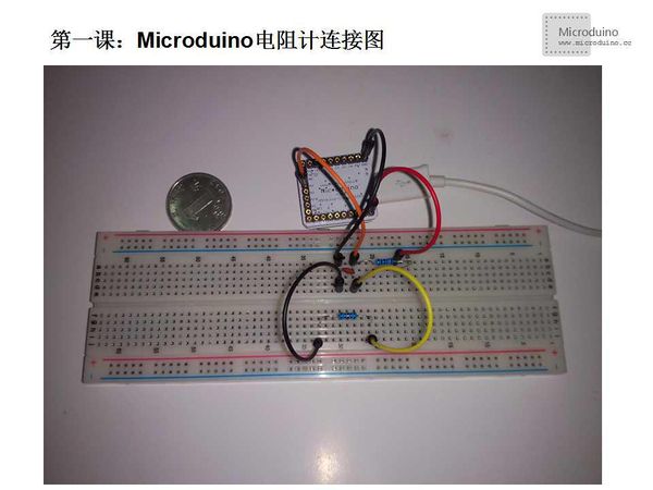
| − | Step | + | Step 2: Connect the circuit, as follows: |
[[File:第一课-Microduino电阻计连接图.jpg|600px|center|thumb]] | [[File:第一课-Microduino电阻计连接图.jpg|600px|center|thumb]] | ||
In figure, the upper resistor is 20k reference resistor, and the low registor is the measured one. | In figure, the upper resistor is 20k reference resistor, and the low registor is the measured one. | ||
| − | Step | + | Step 3: Run program |
| − | Step | + | Step 4: As figure shows, put the yellow line and black line to both end of the resistance, serial will show the resistance value. |
[[File:第一课-Microduino电阻计串口显示电阻值.jpg|600px|center|thumb]] | [[File:第一课-Microduino电阻计串口显示电阻值.jpg|600px|center|thumb]] | ||
Latest revision as of 07:45, 12 September 2016
| Language: | English • 中文 |
|---|
Objective
This lesson will teach you how to use Microduino to make a resistance meter. The basic principle is that use the reference resistor, comparing the voltage, then calculate the resistance value. Through testing, using 20k as the base, if the resistance value more than 1k, the result more accurate.
Equipment
- Microduino-Core
- Microduino-FT232R
- Other hardware equipment
- Breadboard Jumper one box
- Breadboard one piece
- 20kΩ resistor one
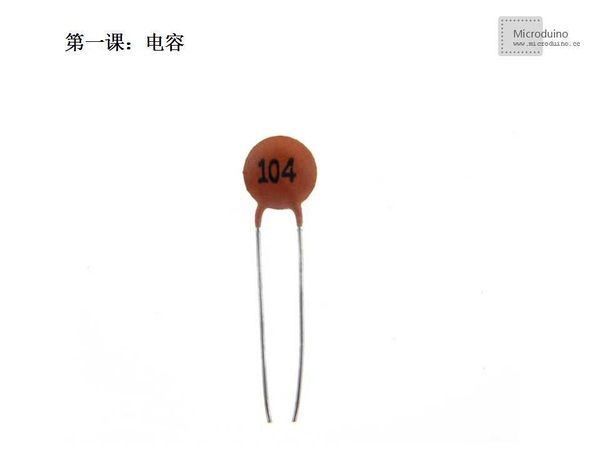
- 104 ceramic capacitor one
- USB Data cable one
Capacitor
brief introduction:
Ceramics is qualitative, 104 is three digits notation, the former two significant figures, the next one is the number of 0. 104 means it is 100000PF, equal to 0.1 uF. Commonly used as bypass capacitor in high frequency or low frequency circuit, and commonly used in power supply decoupling, also has a coupling effect.
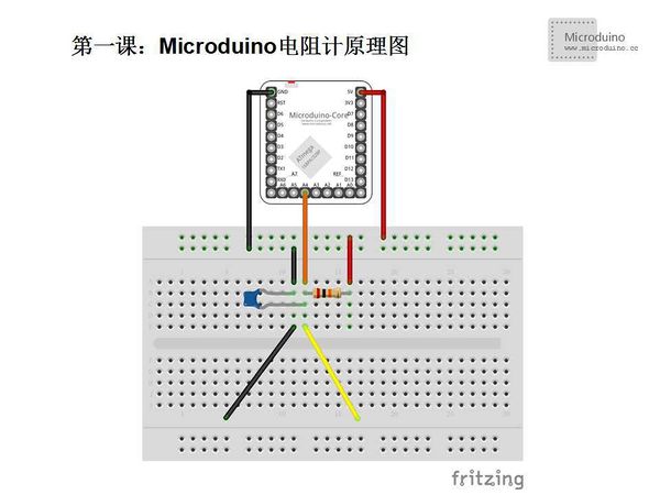
Schematic
You can change the reference resistor according the measure scope, in order to get a good accurate.
Circuit Connection:(Using 104 ceramic capacitor):
Program
Download Program: https://github.com/Microduino/Microduino_Tutorials/tree/master/Microduino_Advanced/MicroduinoResistanceMeter
    #define N 12
    #define basis 20000.0   //Reference resistor

    int potpin = A4;
    float val, r;

    void setup()
    {
        Serial.begin(9600);
    }

    void loop()
    {
        val = analogRead(potpin);
        r = ((basis * 1023.0) / (1023.0 - val)) - basis;
        delay(100);
        Serial.print(" R:  ");
        if(filter() >= 1000)
        {
            if(filter() >= 500.0*1000.0)
            {
                Serial.println("Infinity!!");
            }
            else
            {
                Serial.print(filter() / 1000.0);
                Serial.println("K ohm");
            }
        }

        else
        {
            Serial.print(filter());
            Serial.println(" ohm");
        }
    }

	//Filtering algorithm, use the average filtering algorithm
    float filter()
    {
        float sum = 0;
        for(int count = 0; count < N; count++)
        {
            sum += r;
            delay(5);
        }
        return (float)(sum / N);
    }
Debug
Step 1: Copy the code to IDE, and compile it
Step 2: Connect the circuit, as follows:
In figure, the upper resistor is 20k reference resistor, and the low registor is the measured one.
Step 3: Run program
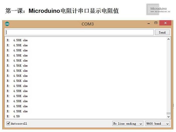
Step 4: As figure shows, put the yellow line and black line to both end of the resistance, serial will show the resistance value.
You also can change to other object to test the resistance, such as soap, a damp cloth and so on.
Result
Serial will show the resistance value.


