Difference between revisions of "Lesson 5--Microduino Simulates Computer Keyboard"
(Created page with "{{Language|第五课--Microduino 模拟电脑键盘}} {| style="width: 800px;" |- | ==Objective== This toturial will use the Microduino to simulate a keyboard, you can input t...") |
(→Program) |
||
| Line 41: | Line 41: | ||
==Program== | ==Program== | ||
| + | Download program: | ||
| + | https://github.com/Microduino/Microduino_Tutorials/tree/master/Microduino_Advanced/MicroduinoAnologKeyborad | ||
| + | |||
<source lang="cpp"> | <source lang="cpp"> | ||
Revision as of 07:46, 29 March 2014
| Language: | English • 中文 |
|---|
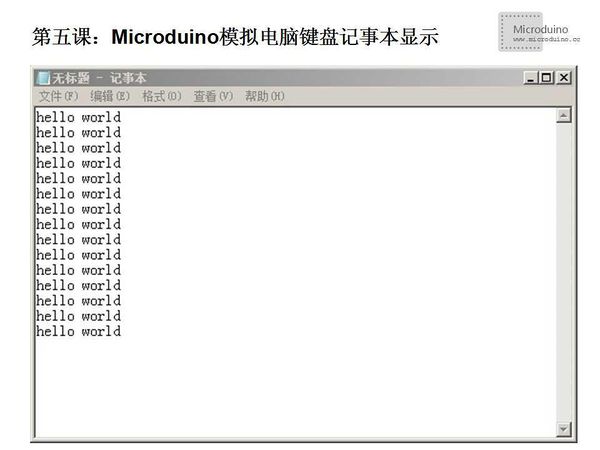
ObjectiveThis toturial will use the Microduino to simulate a keyboard, you can input the "hello world" in notepad. Equipment
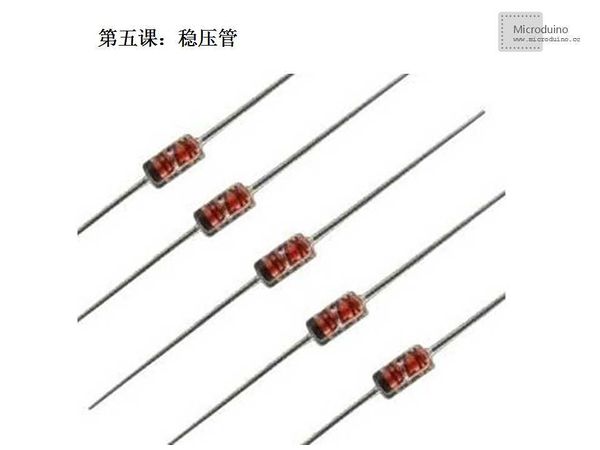
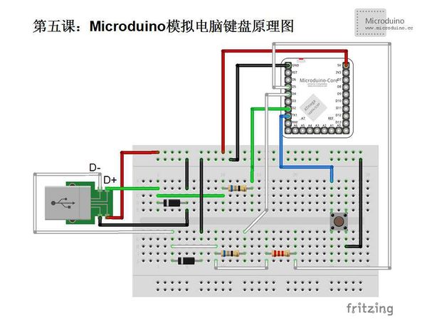
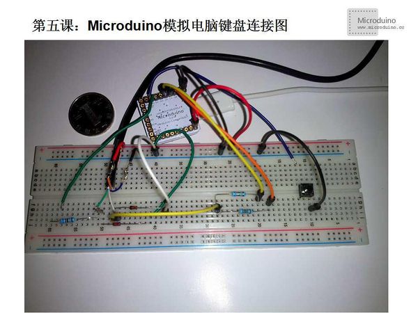
Voltage regulator tube introduction: Voltage regulator diode (also called zener diode) is a kind of silicon surface contact type crystal diode which made of silicon, voltage regulator tube for short. The diode is a high resistance semiconductor devices until the critical reverse breakdown voltage. Before voltage regulator tube wase reverse breakdown, in a certain range of current (or within a certain range power consume), terminal voltage is almost a constant and show the stable voltage characteristic, therefore widely used in the stabilized voltage supply and limiting circuit. Voltage regulator diode is devided according to the breakdown voltage, because of this characteristic, voltage regulator tube is mainly used as stabilizer or voltage reference element. Voltage regulator diode can be used in series together at higher voltage, and then obtain more stable voltage SchematicSchematic introduction: 1. Two 68Ω registor play a current-limiting and protection function, prevent accidents in case of damage to the computer's USB port or microcomputer port. 2. 2.2kΩ is the pull up resistors, used to distinguish the state of the bus. If the pull-up resistor connects to the D+ and + 5v, it is a high speed USB device, otherwise connects to D- and +5 v, used as the low speed device. The keyboard transmission rate isn't high in our experiment, so connenct to D- as the low speed device. 3. Connect to D+ and D-'s 3.6 V voltage regulator diode D1 and D2 have the effect of limiting the level on the cable. Because the USB specification specified that the voltage levle range on the D + and D is 3.0 V to 3.6 V, and the output level of AVR microcontroller is Vcc. If the MCU's Vcc is 5 v, in the absence of D1 and D2 will cause voltage level mismatch, which can cause unable to correctly recognize the USB device in many computer. If the user's system Vcc between 3.0 V and 3.6 V, you can omit the two voltage regulator diode. So you also can see the user's system Vcc must be higher than 3v. 4. Due to the low speed AVRUSB need 1.5 MHz clock, and MCU's every 8 instruction can accurately complete a collection of data bits. So AVRUSB's minimum microcontroller clock frequency is 12 MHZ. And you also can use 12 MHz, 12.8 MHz,15 MHz, 16 MHz and 16.5 MHz and 20 MHz clock frequency, and doesn't support others. So if you use the small system to make the simulated keyboard, ATMega8L doesn't work. ProgramDownload program: https://github.com/Microduino/Microduino_Tutorials/tree/master/Microduino_Advanced/MicroduinoAnologKeyborad /*
Microduino simulate keyboard
Function description:Plug in the simulate keyboard, open the notepad, then press the button, will print the "HELLO WORKD" in notepad
Connect method:
Microduino D2 connects to 68Ω registor, then connects to USB D+
Microduino D4 connects to 68Ω registor, then connects to USB D-
Microduino D5 connects to 2.2kΩ registor, then connects to USB D-
Microduino D2 connects to 3.6v voltage regulator tube and then connects to GND
Microduino D4 connects to 3.6v voltage regulator tube and then connects to GND
+5v connects to USB VCC
GND connects to USB GND
Microduino D1 connects to a button and then connects to GND
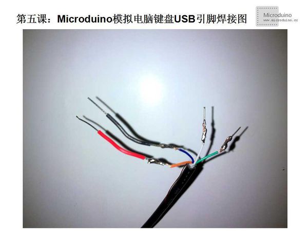
Note:USB color line sequence(Because each manufacturer is different, not necessarily accurate, only for reference)
*USB keyboard/mouse:| *USB interface
White<->VCC | Red<->VCC
Orange<->D- | White<->D-
Green<->D+ | Green<->D+
Bule<->GND | Black<->GND
*/
#include "UsbKeyboard.h"
int KEYPIN = 1; //Button connects to D1 pin, and also can connects to other pin
void setup()
{
TIMSK0 &= !(1 << TOIE0);
pinMode(KEYPIN, INPUT);
digitalWrite(KEYPIN, HIGH);
}
void loop()
{
UsbKeyboard.update();
if(digitalRead(KEYPIN) == HIGH)
{
delay(100);
if(digitalRead(KEYPIN) == LOW)
{
UsbKeyboard.sendKeyStroke(KEY_H);
UsbKeyboard.sendKeyStroke(KEY_E);
UsbKeyboard.sendKeyStroke(KEY_L);
UsbKeyboard.sendKeyStroke(KEY_L);
UsbKeyboard.sendKeyStroke(KEY_O);
UsbKeyboard.sendKeyStroke(KEY_SPACE);
UsbKeyboard.sendKeyStroke(KEY_W);
UsbKeyboard.sendKeyStroke(KEY_O);
UsbKeyboard.sendKeyStroke(KEY_R);
UsbKeyboard.sendKeyStroke(KEY_L);
UsbKeyboard.sendKeyStroke(KEY_D);
UsbKeyboard.sendKeyStroke(KEY_ENTER);
}
}
}DebugFirst introduce the library, need uncompress it then copy to libraries folder of arduinoIDE, then restart the arduinoIDE to load this library. Arduino library: http://soft1.wmzhe.com/download/Ansifa2012/Arduino/UsbKeyboard.zip Note: 1、In UsbKeyboard library, you can change the pin defination in file usbconfig.h, the following is a general explaination (The PORTD is AVR MCU's PORTD, you can find the Arduino's corresponding pin from Arduino's schematic): #define USB_CFG_IOPORTNAME D USB input/output pin, uses AVR MCU's PORTD. If change to B, that will use PORTB #define USB_CFG_DMINUS_BIT 4 USB's D- connects to the fourth bit PD4 of PORTD, corresponding to Arduino's D4 #define USB_CFG_DPLUS_BIT 2 USB's D+ connects to the second bit PD2 of PORTD, correspondign to Arduino's D2 #define USB_CFG_PULLUP_IOPORTNAME D USB pull up pin connnecs to AVR MCU's PORTD, If change to B, that will use PORTB #define USB_CFG_PULLUP_BIT 5 USB pull up registor connects to the fifth bit PD5 of PORTD, corresponding to Arduino's D5 2. In UsbKeyboard librayr's file UsbKeyboard.h, defines the simulate key value #define KEY_A 4 #define KEY_B 5 #define KEY_C 6 #define KEY_D 7 #define KEY_E 8 This doesn't cover all cases. Actually through the testing, this keyboard can simulate all key value except Power, Sleep and Pause. For example, direction key right,left, up and down corresponding to number 79,80,81 and 82. UsbKeyboard.sendKeyStroke(79); UsbKeyboard.sendKeyStroke(81); Becuase there are many case, we can't list all of them, you can download the software "KeyboardTest" to test different key value. Step 1:Copy the code to IDE and compile it Step 2:Set up circuti, as following: Step 3:Run program Step 4:Unplug the downlaod program's USB, plug in the another USB show on schematci, open the notepad, and press the button, the notepad will show as follows: ResultPress the button, the notepad will show "hello world" Video |
