Difference between revisions of "Lesson 23--Microduino Digital Tube Clock"
(→Debug) |
|||
| Line 18: | Line 18: | ||
==Debug== | ==Debug== | ||
*Step 1: | *Step 1: | ||
| − | Measure the four digital tube clock pin. Digital tube has different specification | + | Measure the four digital tube clock pin. Digital tube has different specification. |
| + | |||
| − | |||
*Step 2: | *Step 2: | ||
| Line 47: | Line 47: | ||
==Video== | ==Video== | ||
| − | |||
|} | |} | ||
Revision as of 08:58, 8 July 2016
| Language: | English • 中文 |
|---|
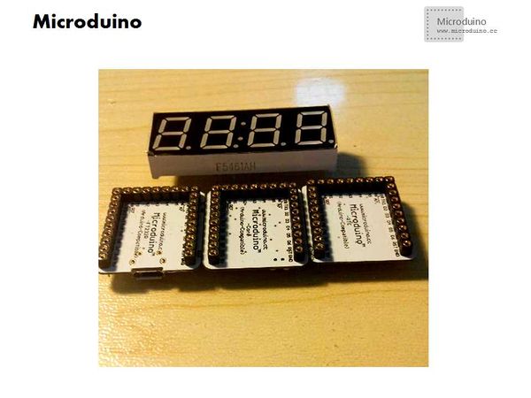
ContentsObjectiveThis tutorial will teach you use the Microduino RTC module to dispaly time on 4 digit tubes. Equipment
ProgramDigit tube program download: Debug
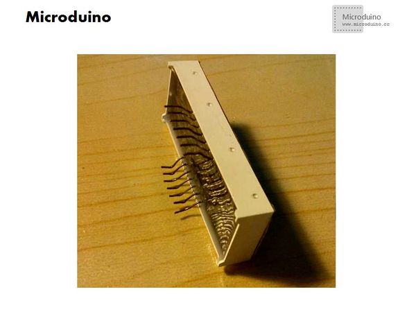
Measure the four digital tube clock pin. Digital tube has different specification.
Insert the digital tube to Microduino core. Installation method is top row connect to D0 - D6, botton row connect to D7 - D13.
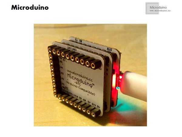
Stack the Microduino-USBTTL, Microduino Core and Microduino RTC together.
Before download program, can't overlay digital tube. Becuase if the digital tube connect to the serial port pin, keep the serial port pin voltage as low level, will be about 0.7 V, which will cause the program download fail. Because digital tube pin may be different, so you may need to change the program.
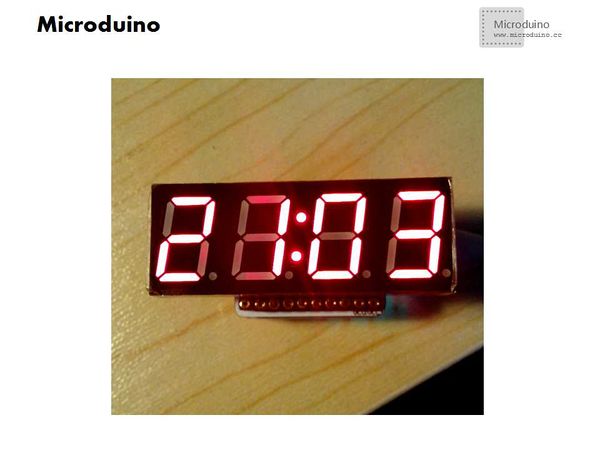
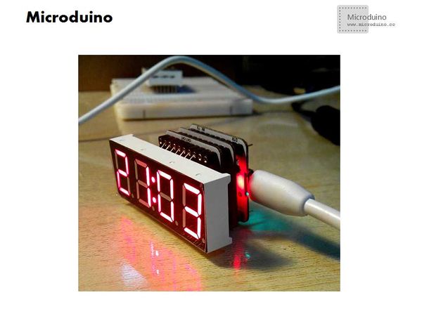
ResultAfter download program, the digit tube will dispaly time. Video |
