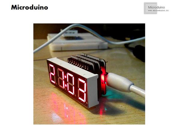
Difference between revisions of "Lesson 23--Microduino Digital Tube Clock"
| Line 4: | Line 4: | ||
| | | | ||
==Objective== | ==Objective== | ||
| − | This tutorial will teach you use the Microduino RTC module to | + | This tutorial will teach you use the Microduino RTC module to display time on 4 digit tubes. |
==Equipment== | ==Equipment== | ||
*'''[[Microduino-Core]]''' | *'''[[Microduino-Core]]''' | ||
| Line 17: | Line 17: | ||
==Debug== | ==Debug== | ||
| − | *Step | + | *Step 1: |
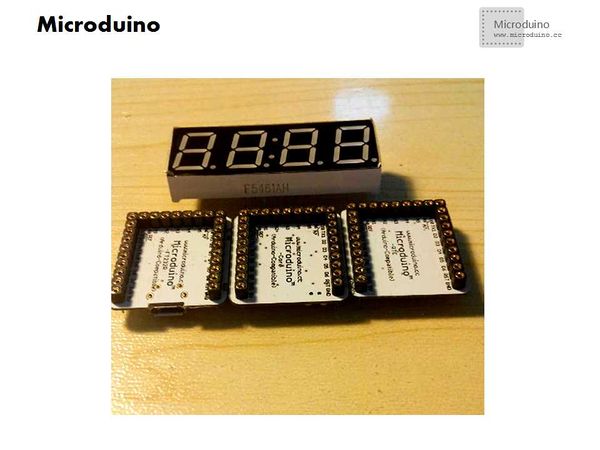
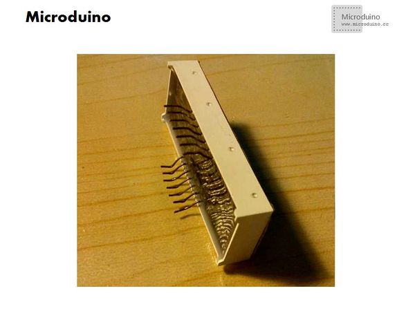
Measure the four digital tube clock pin. Digital tube has different specification. | Measure the four digital tube clock pin. Digital tube has different specification. | ||
| − | *Step | + | *Step 2: |
| − | Insert the digital tube to Microduino core. Installation method is top row connect to D0 - D6, | + | Insert the digital tube to Microduino core. Installation method is top row connect to D0 - D6, button row connect to D7 - D13. |
[[File:RTCTime_1.jpg|600px|center|RTCTime]] | [[File:RTCTime_1.jpg|600px|center|RTCTime]] | ||
| − | *Step | + | *Step 3: |
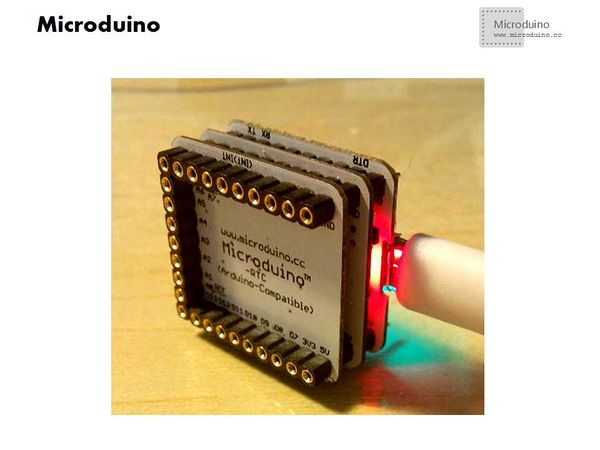
Stack the Microduino-USBTTL, Microduino Core and Microduino RTC together. | Stack the Microduino-USBTTL, Microduino Core and Microduino RTC together. | ||
[[File:RTCTime_2.jpg|600px|center|RTCTime]] | [[File:RTCTime_2.jpg|600px|center|RTCTime]] | ||
| − | *Step | + | *Step 4: Download program |
| − | Before download program, can't overlay digital tube. | + | Before download program, can't overlay digital tube. Because if the digital tube connect to the serial port pin, keep the serial port pin voltage as low level, will be about 0.7 V, which will cause the program download fail. |
Because digital tube pin may be different, so you may need to change the program. | Because digital tube pin may be different, so you may need to change the program. | ||
**Program uses common anode clock digital tube, if want to light the common cathode digital tube, need to change the LOW to HIGH and HIGH to LOW in function duanma(). And in the daytime() function, add a "~" before the data, such as leddisplay(data[timehours]), it need to be changed to leddisplay(~ data[timehours]); | **Program uses common anode clock digital tube, if want to light the common cathode digital tube, need to change the LOW to HIGH and HIGH to LOW in function duanma(). And in the daytime() function, add a "~" before the data, such as leddisplay(data[timehours]), it need to be changed to leddisplay(~ data[timehours]); | ||
| Line 41: | Line 41: | ||
==Result== | ==Result== | ||
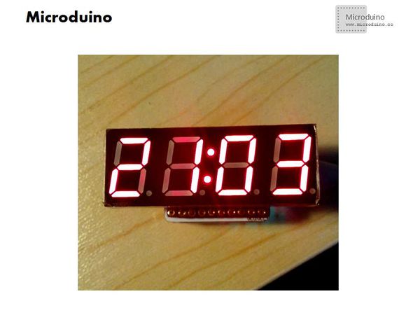
| − | After download program, the digit tube will | + | After download program, the digit tube will display time. |
[[File:RTCTime_3.jpg|600px|center|RTCTime]] | [[File:RTCTime_3.jpg|600px|center|RTCTime]] | ||
[[File:RTCTime_4.jpg|600px|center|RTCTime]] | [[File:RTCTime_4.jpg|600px|center|RTCTime]] | ||
Latest revision as of 08:29, 12 September 2016
| Language: | English • 中文 |
|---|
ContentsObjectiveThis tutorial will teach you use the Microduino RTC module to display time on 4 digit tubes. Equipment
ProgramDigit tube program download: Debug
Measure the four digital tube clock pin. Digital tube has different specification.
Insert the digital tube to Microduino core. Installation method is top row connect to D0 - D6, button row connect to D7 - D13.
Stack the Microduino-USBTTL, Microduino Core and Microduino RTC together.
Before download program, can't overlay digital tube. Because if the digital tube connect to the serial port pin, keep the serial port pin voltage as low level, will be about 0.7 V, which will cause the program download fail. Because digital tube pin may be different, so you may need to change the program.
ResultAfter download program, the digit tube will display time. Video |
