Difference between revisions of "Lesson 25--Microduino 5*7 Lattice Static Display"
(Created page with "{{Language|第二十五课--Microduino 5*7点阵静态显示}} {| style="width: 800px;" |- | ==Objective== This experiment will introduce how to use the Microduino I/O port to...") |
|||
| Line 26: | Line 26: | ||
If you don't have hte lattice pin diagram, measure it by yourself. Detailed step, please refer to 8*8 lattice. | If you don't have hte lattice pin diagram, measure it by yourself. Detailed step, please refer to 8*8 lattice. | ||
| − | + | ||
===Set up circuit=== | ===Set up circuit=== | ||
Revision as of 05:58, 13 July 2016
| Language: | English • 中文 |
|---|
ContentsObjectiveThis experiment will introduce how to use the Microduino I/O port to control 5*7 lattice and without drive chip. Equipment
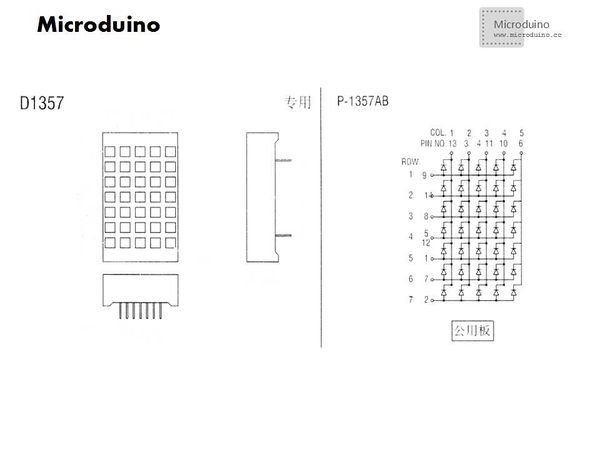
Schematic
Common cathode:All the cathode of LED connect together, and use high level to light the LED. Common anode:All the anode of LED connect together, and use low level to light the LED. DebugMeasure lattice pinIf you don't have hte lattice pin diagram, measure it by yourself. Detailed step, please refer to 8*8 lattice.
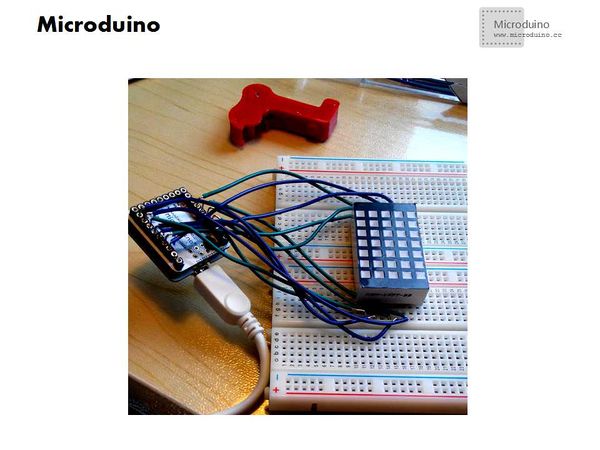
Set up circuit
Program
Step 1:Download test program, and open it; Step 2:Select the board type and download directly, after download a picture will be shown on lattice
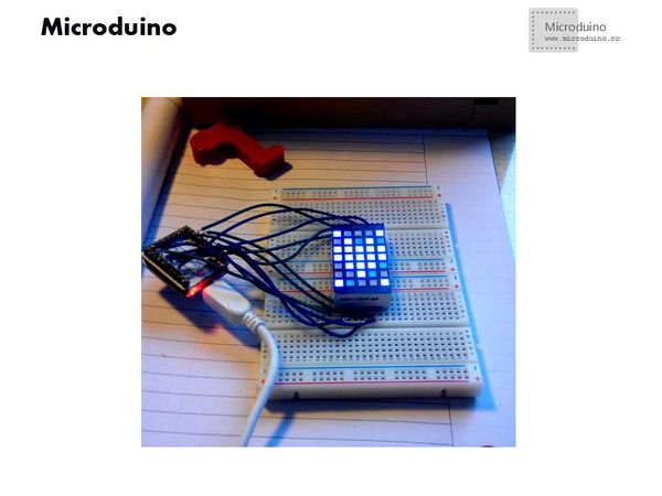
Change the fontDetailed information, please refer to:http://www.microduino.cc/wiki/index.php?title=%E7%AC%AC%E4%BA%8C%E8%AF%BE--Microduino_OLED%E4%BD%BF%E7%94%A8/zh Note:Need to replace modulus with image model, and new a 5*7 image. Draw a image, then the modulus way changed to: Yin, column type, reverse. Change the font code in data[], download directly and then display the new image on lattice. ResultBy testing, lattice can display an image and each LED's brightness is uniform, very beautiful. Video |


