Difference between revisions of "Microduino Pulse measuring instrument"
From Microduino Wiki
(→Outline) |
|||
| Line 4: | Line 4: | ||
| | | | ||
==Outline== | ==Outline== | ||
| − | * | + | *Project: Microduino pulse measuring instrument |
| − | * | + | *Objective: Use pulse sensor and Microduino to measure the pulse. |
| − | * | + | *Difficulty: High |
| − | *Time- | + | *Time-consuming: 5 hours |
| − | * | + | *Maker: Microduino Studio-YLB |
==Bill of Materials== | ==Bill of Materials== | ||
| Line 42: | Line 42: | ||
==Debug== | ==Debug== | ||
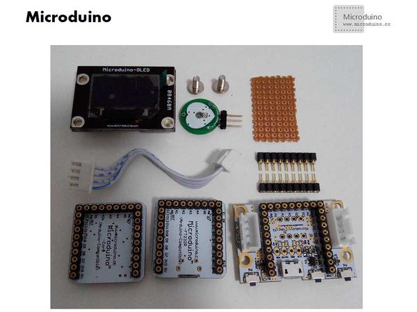
| − | *Step | + | *Step 1: Prepare the experiment equipment |
[[File:Microduino_Heat_all.jpg||600px|center|thumb]] | [[File:Microduino_Heat_all.jpg||600px|center|thumb]] | ||
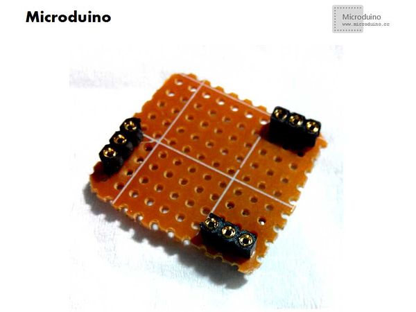
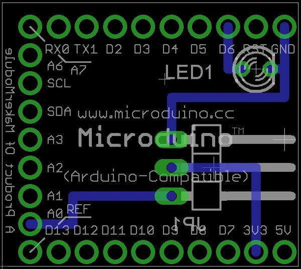
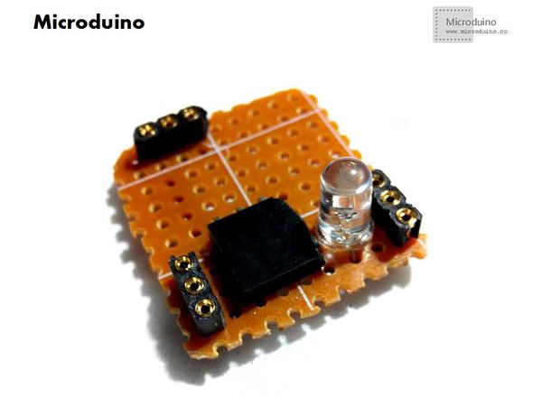
| − | *Step | + | *Step 2: Build adapter board |
| − | **Cut a certain specification size | + | **Cut a certain specification size pegboard; |
| − | **Weld the row needles, using VCC(3.3V), GND, A0 abd | + | **Weld the row needles, using VCC(3.3V), GND, A0 abd D6; |
[[File:Microduino_Welding1.jpg||600px|center|thumb]] | [[File:Microduino_Welding1.jpg||600px|center|thumb]] | ||
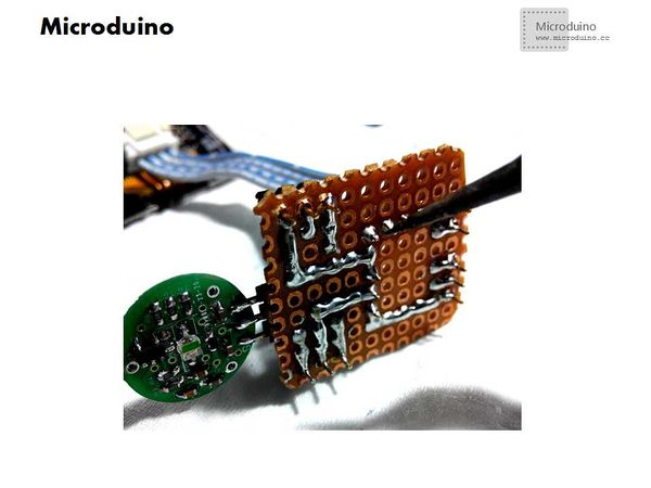
*Make sure the welding position is correct | *Make sure the welding position is correct | ||
| Line 62: | Line 62: | ||
[[File:Microduino_Welding5.jpg||600px|center|thumb]] | [[File:Microduino_Welding5.jpg||600px|center|thumb]] | ||
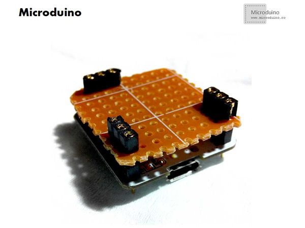
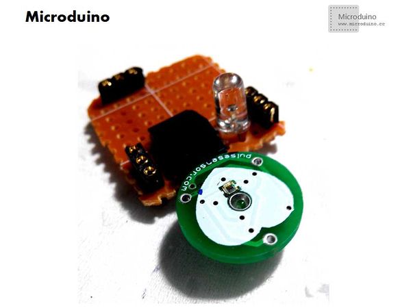
| − | *Step | + | *Step 2: Set up hardware and test whether the welding is correct |
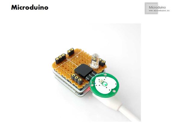
Assembly Microduino Core, Microdino FT232 and welding board, then power on to check if the sensor indicator light. | Assembly Microduino Core, Microdino FT232 and welding board, then power on to check if the sensor indicator light. | ||
[[File:Microduino_Setup0.jpg||600px|center|thumb]] | [[File:Microduino_Setup0.jpg||600px|center|thumb]] | ||
| Line 72: | Line 72: | ||
*Start IDE, open "Microduino_Pulse_measurement" program, compile it and then download: | *Start IDE, open "Microduino_Pulse_measurement" program, compile it and then download: | ||
| − | *Step | + | *Step 3: Test |
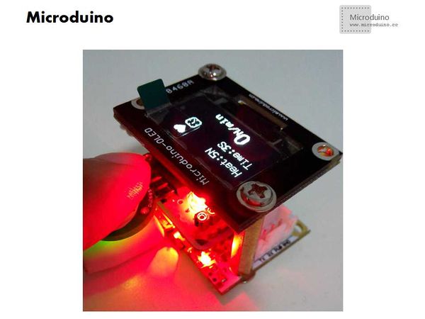
Put the finger on the sensor, observe whether LED is in a simulated heart beating | Put the finger on the sensor, observe whether LED is in a simulated heart beating | ||
[[File:Microduino_Setup2.jpg||600px|center|thumb]] | [[File:Microduino_Setup2.jpg||600px|center|thumb]] | ||
Latest revision as of 09:25, 12 September 2016
| Language: | English • 中文 |
|---|
Outline
Bill of Materials
DocumentDebug
Assembly Microduino Core, Microdino FT232 and welding board, then power on to check if the sensor indicator light.
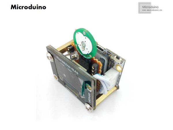
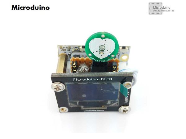
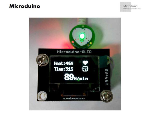
Put the finger on the sensor, observe whether LED is in a simulated heart beating OLED data can be seen in changes, including the heartbeat, time, times in one minute. From detection to the heart of the first ten seconds is expected to jump how many times in one minute. Result
Issues need to pay attention
|
