Difference between revisions of "Gyroscope"
(Created page with "{{Language | 陀螺仪}} {| style="width: 800px;" |- | ==Objective== This tutorial will use the Microduino-10DOF module's gyroscope and accelerometer sensor to measure data, a...") |
|||
| Line 25: | Line 25: | ||
==Debug== | ==Debug== | ||
| − | Step | + | Step 1: Set up hardware system, as follows: |
[[File:AtmosphericDataCollectionConnectionDiagram.jpg|600px|center|thumb]] | [[File:AtmosphericDataCollectionConnectionDiagram.jpg|600px|center|thumb]] | ||
| Line 34: | Line 34: | ||
Microduino: | Microduino: | ||
| − | //Get the gyroscope and accelerometer sensor's data and output to serial to | + | //Get the gyroscope and accelerometer sensor's data and output to serial to display. |
void loop() { | void loop() { | ||
| Line 51: | Line 51: | ||
//Display Microduino received data in screen. | //Display Microduino received data in screen. | ||
| − | Function | + | Function description: |
readSensors() //Read the sensor data | readSensors() //Read the sensor data | ||
| Line 57: | Line 57: | ||
normalize3DVec(float [] vector) //Process the 3d vector | normalize3DVec(float [] vector) //Process the 3d vector | ||
| − | buildBoxShape() //Setup the | + | buildBoxShape() //Setup the shape of box |
drawCube() //Draw the box | drawCube() //Draw the box | ||
Latest revision as of 09:15, 13 September 2016
| Language: | English • 中文 |
|---|
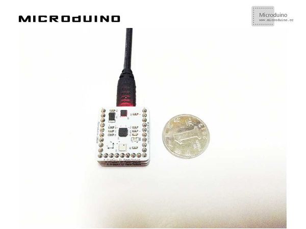
ObjectiveThis tutorial will use the Microduino-10DOF module's gyroscope and accelerometer sensor to measure data, and then display the data in Processing. Equipment
SchematicUse the Microduino-10DOF module's gyroscope and accelerometer sensor directly. ProgramRefers to MPU6050Microduino processingGyro DebugStep 1: Set up hardware system, as follows: Step 2: Explain the code: This example needs two parts code, one is Processing and the other is Microduino. Microduino: //Get the gyroscope and accelerometer sensor's data and output to serial to display. void loop() {
accelgyro.getMotion6(&ax, &ay, &az, &gx, &gy, &gz);
sprintf(str, "%d,%d,%d,%d,%d,%d,%d", ax, ay, az, gx, gy, gz);
Serial.print(str);
Serial.write(byte(10));
delay(20);
}
Processing: //Get the first serial port data. myPort = new Serial(this, Serial.list()[0], 9600); // first COM port //Display Microduino received data in screen. Function description: readSensors() //Read the sensor data normalize3DVec(float [] vector) //Process the 3d vector buildBoxShape() //Setup the shape of box drawCube() //Draw the box getInclination() //Get the angle
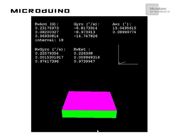
Step 4: After running, rotate the Microduino module and observe Microduino's display. ResultA box will be displayed in screen, it can simulate the Microduino's posture, as follows: Video |

