Difference between revisions of "Multimeter Simulation"
(→Debugging) |
|||
| Line 4: | Line 4: | ||
==Objective== | ==Objective== | ||
| − | The course will show you how to simulate a multimeter with Microduino. The reading of the | + | The course will show you how to simulate a multimeter with Microduino. The reading of the "multimeter" will be displayed on Processing. |
==Equipment== | ==Equipment== | ||
| Line 31: | Line 31: | ||
==Debugging== | ==Debugging== | ||
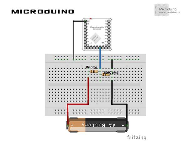
| − | Step | + | Step 1: Building the schematic diagram according to hardware environment, as follows: |
[[File:AnalogVoltmeterConnection.jpg|600px|center|thumb]] | [[File:AnalogVoltmeterConnection.jpg|600px|center|thumb]] | ||
| − | Step | + | Step 2: Here is the code we need: |
The code of the two ends (Processing and Microduino) | The code of the two ends (Processing and Microduino) | ||
| Line 117: | Line 117: | ||
| − | Step | + | Step 3: Uploading the code and get it compiled successfully. |
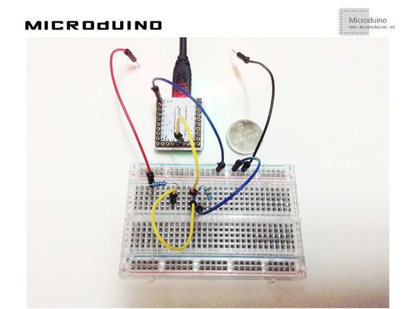
| − | Step | + | Step 4: Finding a battery or something similar and putting it between the red and the black lines, then watching the reading on the screen. Please refer to the image above. |
==Result== | ==Result== | ||
Latest revision as of 09:17, 13 September 2016
ObjectiveThe course will show you how to simulate a multimeter with Microduino. The reading of the "multimeter" will be displayed on Processing. Equipment
Schematic DiagramThe schematic diagram adopts A2 pin. There are four channels totally, corresponding to the pins of A0, A1, A2, A3 respectively. The voltage reading will be displayed in Channel One. ProgramReferring to AnalogVoltmeter AnalogVoltmeterProcessing DebuggingStep 1: Building the schematic diagram according to hardware environment, as follows:
The code of the two ends (Processing and Microduino) Microduino: //The voltage value will be received by Processing via serial port output void loop()
{
// take a number of analog samples and add them up
while (sample_count < NUM_SAMPLES) {
// sample each channel A2 to A5
for (l_cnt = 0; l_cnt < 4; l_cnt++) {
sum[l_cnt] += analogRead(A2 + l_cnt);
}
sample_count++;
delay(10);
}
// calculate the voltage for each channel
for (l_cnt = 0; l_cnt < 4; l_cnt++) {
voltage[l_cnt] = ((float)sum[l_cnt] / (float)NUM_SAMPLES * V_REF) / 1024.0;
}
// each voltage is multiplied by the resistor network
// division factor to calculate the actual voltage
voltage[0] = voltage[0] * DIV_1;
voltage[1] = voltage[1] * DIV_2;
voltage[2] = voltage[2] * DIV_3;
voltage[3] = voltage[3] * DIV_4;
// send voltages to Processing application via serial port / USB
// voltage 1 - A (pin A2)
Serial.print("A ");
Serial.print(voltage[0], 1);
Serial.print("V ");
// voltage 2 - B (pin A3)
Serial.print("B ");
Serial.print(voltage[1], 1);
Serial.print("V ");
// voltge 3 - C (pin A4)
Serial.print("C ");
Serial.print(voltage[2], 1);
Serial.print("V ");
// voltage 4 - D (pin A5)
Serial.print("D ");
Serial.print(voltage[3], 1);
Serial.print("V ");
Serial.println("");
delay(10);
// reset count and sums
sample_count = 0;
for (l_cnt = 0; l_cnt < 4; l_cnt++) {
sum[l_cnt] = 0;
}
}
Processing: //After getting the data of the first serial port println(Serial.list()); // modify Serial.list()[0] to select correct serial port ser_port = new Serial(this, Serial.list()[0], 9600);
Serial Event: serialEvent(Serial p) Displaying the channel and voltage: voltage (int channel, String volts) Drawing graph axis: DrawGraphAxis(int pos_x, int pos_y, int width, int height) Drawing graph: DrawGraph (String voltage, int channel, int pos_x, int pos_y, int scale) Drawing scale and radio box: DrawScaleSelect (int x_pos, int y_pos, int scale)
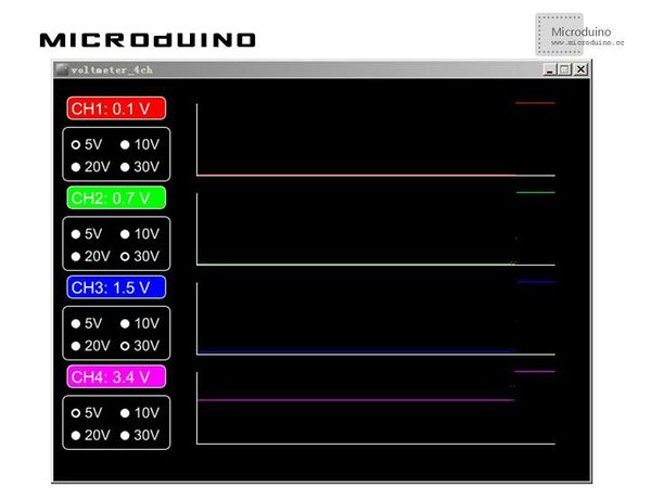
Step 3: Uploading the code and get it compiled successfully. Step 4: Finding a battery or something similar and putting it between the red and the black lines, then watching the reading on the screen. Please refer to the image above. ResultThe voltage reading of the A5 pin will be displayed in Channel Four on the screen, just as follows:
Video |


