Difference between revisions of "Microduino-Quadcopter Tutorial"
| Line 19: | Line 19: | ||
===System Structure=== | ===System Structure=== | ||
[[File:jiagou11.PNG|center|300px]] | [[File:jiagou11.PNG|center|300px]] | ||
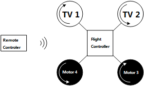
| − | As the picture shows, the Quadopcter consists of a remote controller, a flight controller and four motors. And for the flight controller includes a | + | As the picture shows, the Quadopcter consists of a remote controller, a flight controller and four motors. And for the flight controller includes a microcontroller, a remote control signal receiving module, a motor driving module and sensor modules (A gyroscope, an accelerator, an electronic compass and a GPS module). |
<br> | <br> | ||
| Line 59: | Line 59: | ||
The three kinds of motion mentioned above all happen in the directions of the three axes. Next, we'll introduce the motion around the three axes. | The three kinds of motion mentioned above all happen in the directions of the three axes. Next, we'll introduce the motion around the three axes. | ||
|- | |- | ||
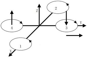
| − | |Yawing motion is the rotation in the horizontal direction, | + | |Yawing motion is the rotation in the horizontal direction, namely rotation around the Z-axis. |
During the rotation, it will form an anti-torque opposite to the rotation due to air resistance. Yawing rotation is realized by using the reverse torque. When the aircraft suspends, the speed of the four motors is the same, which can offset torque in both horizontal and vertical direction, and achieve balance. When the speed of the four motors is different, unbalanced anti-torque will cause horizontal rotation and the aircraft will deviate from the route. As the picture shows, by increasing the speed of the motor 1 and 2, and decreasing that of the motor 3 and 4, the clockwise anti-torque generated by the motor 1 and 2 will be larger than the counter clockwise anti-torque generated by the motor 3 and 4, causing clockwise rotation of the aircraft horizontally and generating no vertical displacement when there is no change in the thrust upside. | During the rotation, it will form an anti-torque opposite to the rotation due to air resistance. Yawing rotation is realized by using the reverse torque. When the aircraft suspends, the speed of the four motors is the same, which can offset torque in both horizontal and vertical direction, and achieve balance. When the speed of the four motors is different, unbalanced anti-torque will cause horizontal rotation and the aircraft will deviate from the route. As the picture shows, by increasing the speed of the motor 1 and 2, and decreasing that of the motor 3 and 4, the clockwise anti-torque generated by the motor 1 and 2 will be larger than the counter clockwise anti-torque generated by the motor 3 and 4, causing clockwise rotation of the aircraft horizontally and generating no vertical displacement when there is no change in the thrust upside. | ||
| Line 91: | Line 91: | ||
|Since the four-motor combination control can only reach to six directions, which is an under actuated system. So here we must have a flight controller to control the whole system. | |Since the four-motor combination control can only reach to six directions, which is an under actuated system. So here we must have a flight controller to control the whole system. | ||
|- | |- | ||
| − | |In the flight controllers, sensors such as gyroscope and accelerator are dispensable. Micro controller can calculate data from the two sensors, get the current aircraft's attitude and then adjust the rotation rate with algorithms such PID to keep the stability. Sure you can add an electronic compass to get the direction or a GPS module to get the geographic location. Simply speaking, the quadcopter is system with two closed-loops to control---the large loop gets input volume from the remote receiving device and the small loop | + | |In the flight controllers, sensors such as gyroscope and accelerator are dispensable. Micro controller can calculate data from the two sensors, get the current aircraft's attitude and then adjust the rotation rate with algorithms such PID to keep the stability. Sure you can add an electronic compass to get the direction or a GPS module to get the geographic location. Simply speaking, the quadcopter is system with two closed-loops to control---the large loop gets input volume from the remote receiving device and the small loop acquires input volume from the attitude sensor. |
|- | |- | ||
|Generally speaking, the quadcopter kit includes an aircraft and a remote controller, the two of which controls instructions through the CoreRF transmission. | |Generally speaking, the quadcopter kit includes an aircraft and a remote controller, the two of which controls instructions through the CoreRF transmission. | ||
| Line 194: | Line 194: | ||
*Set the flight mode. | *Set the flight mode. | ||
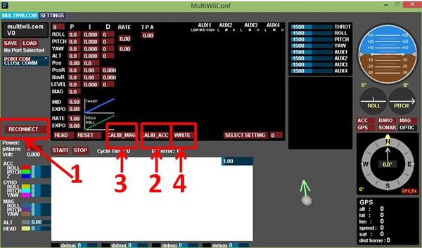
| − | **On the right side of the adjustment of PID, click ”SELECT SETTING”(as the following | + | **On the right side of the adjustment of PID, click ”SELECT SETTING”(as the following figure). |
**Click the left mouse button on the square, and the grey square will change into white. Click the 3 squares as the following picture(which should be grey originally). | **Click the left mouse button on the square, and the grey square will change into white. Click the 3 squares as the following picture(which should be grey originally). | ||
**After setting, click WRITE to write the value into the flight control. | **After setting, click WRITE to write the value into the flight control. | ||
Revision as of 05:14, 26 April 2016
| Language: | English • 中文 |
|---|
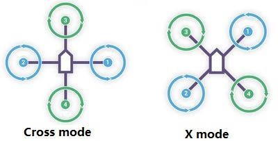
Contents[hide]OutlineQuadcopter is one kind of aircraft that is equipped with four propellers. Similar to the helicopter, it can finish the action of hover and flight. A traditional helicopter uses a main rotor to generate thrust and a tail rotor to offset the torque from the main rotor, namely, | ||||||||||||||||||||||||||||||||||||
| According to the user-defined fore and aft direction of the aircraft, the quadcopter can be divided into the cross mode and X mode. The cross mode means that the fore and aft direction points to a certain propeller and the X mode refers to that the fore and aft direction points to the middle of two propellers.
| ||||||||||||||||||||||||||||||||||||
For most aircraft adopting X mode, the X mode is harder to control but more flexible.
PrincipleSystem StructureAs the picture shows, the Quadopcter consists of a remote controller, a flight controller and four motors. And for the flight controller includes a microcontroller, a remote control signal receiving module, a motor driving module and sensor modules (A gyroscope, an accelerator, an electronic compass and a GPS module).
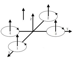
Flying PrincipleVertical MotionVertical motion includes rising or falling vertically. As the text mentioned previously, the quadcopter can keep balance horizontally by four motors maintaining the same rotation rate. As you can see from picture 2.2.1, if the four motors increase to the same speed, the generated thrust will be large enough to overcome the quadcopter weight and rise, and vice versa. Under the condition of no surrounding interruption, the four motors can generate enough thrust to overcome the weight and therefore, the quadcopter can suspend in the air.
| ||||||||||||||||||||||||||||||||||||
| The quadcopter can fly steadily in the vertical direction as long as the four motors maintain the same speed.
Front & Lateral MotionThe motor 1 is the head of the aircraft and the motor 2 is the rear.
Yawing MotionThe three kinds of motion mentioned above all happen in the directions of the three axes. Next, we'll introduce the motion around the three axes. | ||||||||||||||||||||||||||||||||||||
| Yawing motion is the rotation in the horizontal direction, namely rotation around the Z-axis.
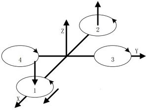
During the rotation, it will form an anti-torque opposite to the rotation due to air resistance. Yawing rotation is realized by using the reverse torque. When the aircraft suspends, the speed of the four motors is the same, which can offset torque in both horizontal and vertical direction, and achieve balance. When the speed of the four motors is different, unbalanced anti-torque will cause horizontal rotation and the aircraft will deviate from the route. As the picture shows, by increasing the speed of the motor 1 and 2, and decreasing that of the motor 3 and 4, the clockwise anti-torque generated by the motor 1 and 2 will be larger than the counter clockwise anti-torque generated by the motor 3 and 4, causing clockwise rotation of the aircraft horizontally and generating no vertical displacement when there is no change in the thrust upside. Pitch and Roll MotionPitch motion refers to the rotation in the Y-axis direction while the roll motion refers to the rotation in the X-axis direction. | ||||||||||||||||||||||||||||||||||||
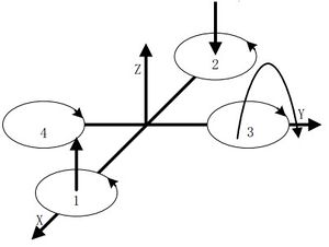
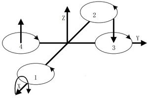
| As the picture shows, by increasing the speed of the motor 1 and decreasing that of the motor 2, and keeping the same of the variable quantity as well as the speed of the motor 3 and 4: The thrust of the head is larger than that of the rear. The unbalanced torque makes the body rise. Similarly, the roll motion is realized by reducing the speed of the motor 1 and increasing that of the motor 2, generating a torque forward. | ||||||||||||||||||||||||||||||||||||
The principle of the roll and pitch motion is the same due to symmetry in the middle. By keeping the speed of the motor 1 and 2 unchanged, and changing the speed of motor 3 and 4, it'll generate unbalanced torque and make the aircraft rotate around the X-axis direction.
Control ProcedureThe remote controller sends out control command, such as take-off or flying left. The control signal is received wirelessly.
| ||||||||||||||||||||||||||||||||||||
| Since the four-motor combination control can only reach to six directions, which is an under actuated system. So here we must have a flight controller to control the whole system. | ||||||||||||||||||||||||||||||||||||
| In the flight controllers, sensors such as gyroscope and accelerator are dispensable. Micro controller can calculate data from the two sensors, get the current aircraft's attitude and then adjust the rotation rate with algorithms such PID to keep the stability. Sure you can add an electronic compass to get the direction or a GPS module to get the geographic location. Simply speaking, the quadcopter is system with two closed-loops to control---the large loop gets input volume from the remote receiving device and the small loop acquires input volume from the attitude sensor. | ||||||||||||||||||||||||||||||||||||
| Generally speaking, the quadcopter kit includes an aircraft and a remote controller, the two of which controls instructions through the CoreRF transmission. | ||||||||||||||||||||||||||||||||||||
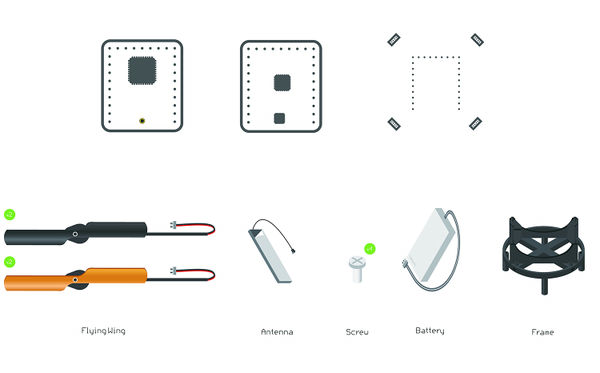
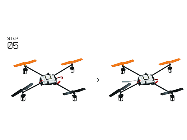
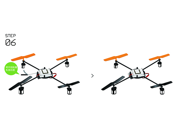
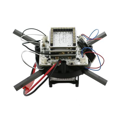
| The quadcopter is composed of a frame, Microduino-CoreRF , Microduino-Motion and other modules. For Microduino-motion, it integrates a three-axis gyroscope + a three-axis accelerator(MPU6040), a magnetic field intensity sensor(HMC5883L) and a digital pressure sensor(BMP180), and have communication through IIC. | ||||||||||||||||||||||||||||||||||||
MPU6050 is the most important attitude sensor with a three-axis accelerator and a three-axis gyroscope integrated inside, which not only offsets adjustment errors for the combination of a three-axis accelerator and a three-axis gyroscope, and also has a built-in low pass filter.
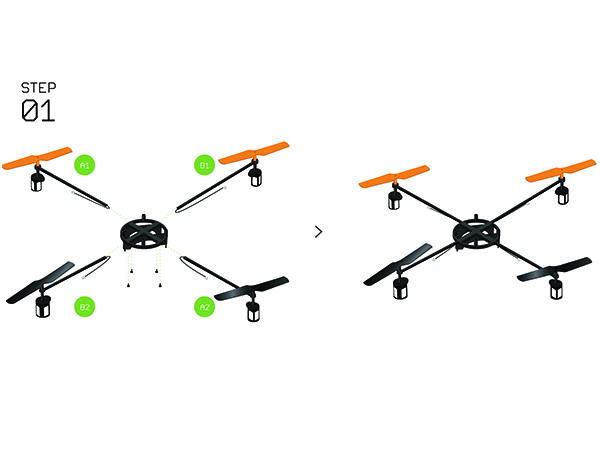
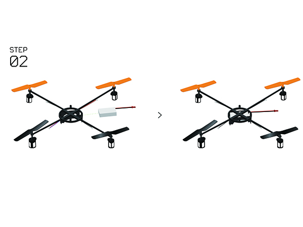
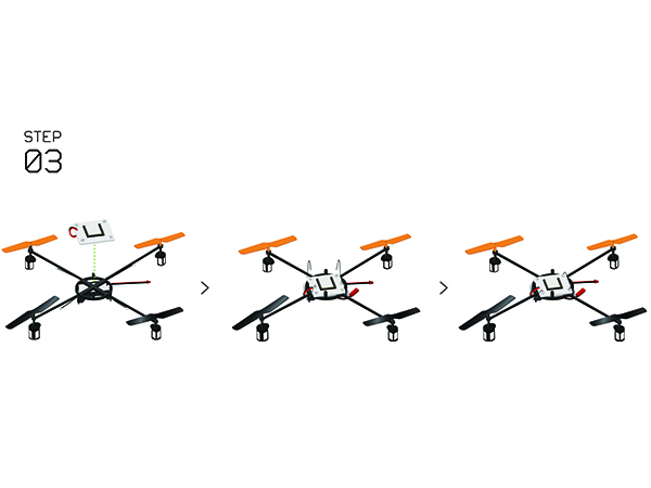
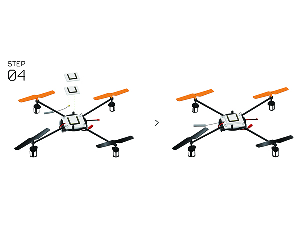
Buildup and DebuggingBill of Materials
Program Download
Programming
Operating InstructionsGuidance of Correcting the Four AxesAutocorrection(Recommend)
Manual Correction
Guidance of Joypad Remote Controller
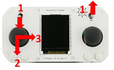
Joypad unlock the four axes
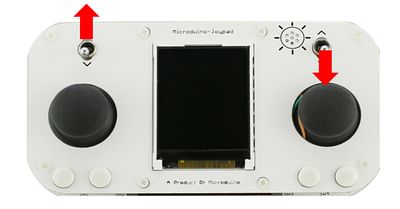
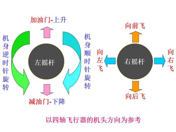
Joypad Controls the Quadcopter
Program DescriptionAttentionAlthough the above contents list a lot of problems that should be paid attention to, they need to be summarized here.
If other problems appear, please put forward in the discussion part. |
