Difference between revisions of "Microduino-Module TFT"
From Microduino Wiki
(→Application) |
|||
| (One intermediate revision by the same user not shown) | |||
| Line 16: | Line 16: | ||
*Adopt 4-wire SPI communication and own its pixel addressing frame buffer | *Adopt 4-wire SPI communication and own its pixel addressing frame buffer | ||
*Few pin and small memory make it suitable for microprocessor use | *Few pin and small memory make it suitable for microprocessor use | ||
| − | *Open hardware circuit design and Arduino compatible | + | *Open hardware circuit design and Arduino compatible programming development environment |
==Specification== | ==Specification== | ||
| − | *Resolution | + | *Resolution ratio: 128*160 |
| − | * | + | *Power: 3.3V |
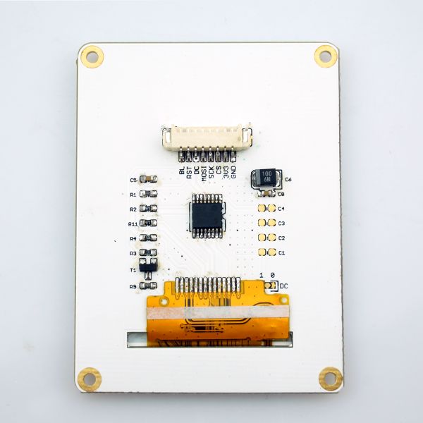
| − | * | + | *Interface: SPI communication and JST_XH connector |
*Pin Description: | *Pin Description: | ||
| Line 40: | Line 40: | ||
|} | |} | ||
==Document== | ==Document== | ||
| − | * | + | *Chip: '''[[File:ST7735.pdf]]''' |
==Development== | ==Development== | ||
| − | *TFT_ST7735 | + | *TFT_ST7735 library: https://github.com/Microduino/Microduino_Tutorials/tree/master/Microduino_Libraries/_01_Microduino_TFT_ST7735 |
| − | *TFT_GFX | + | *TFT_GFX library: https://github.com/Microduino/Microduino_Tutorials/tree/master/Microduino_Libraries/_01_Microduino_TFT_GFX |
The two libraries must be used together. | The two libraries must be used together. | ||
==Application== | ==Application== | ||
| − | *All the hardware | + | *All the hardware needed: Microduino USBTTL, Microduino Core and Microduino TFT; |
| − | *All the software | + | *All the software needed: libraries needed in development and Arduino IDE (version 1.0 and higher) |
| − | *Open IDE and choose the board Microduino-Core (Atmega328P@16M,5V) | + | *Open IDE and choose the board Microduino-Core (Atmega328P@16M, 5V) |
*Basic usage of TFT_ST7735 library example program | *Basic usage of TFT_ST7735 library example program | ||
**Put the two downloaded libraries into Arduino IDE installation folder. (Close all the Arduino IDE windows opened before resetting the Arduino IDE.) | **Put the two downloaded libraries into Arduino IDE installation folder. (Close all the Arduino IDE windows opened before resetting the Arduino IDE.) | ||
**Text and drawings: | **Text and drawings: | ||
| − | ***You can open your first | + | ***You can open your first "graphicstest" test program and meantime, you can connect the wire according the pin description |
***The program can be used to display different color, size and text, and also can be used to draw pictures. | ***The program can be used to display different color, size and text, and also can be used to draw pictures. | ||
**Display images inside the memory card | **Display images inside the memory card | ||
***Prepare a 128*160 bmp picture and put it into the memory car; | ***Prepare a 128*160 bmp picture and put it into the memory car; | ||
***Put the memory card into Microduino-SD modules and stack it with Microduino core module; | ***Put the memory card into Microduino-SD modules and stack it with Microduino core module; | ||
| − | ***If you want to open the last but one | + | ***If you want to open the last but one "spitftbitmapt" test program, you need to change "#define SD_CS 4" to "#define SD_CS 7" and meantime, connect the wire according to pin description and then change the name of "bmpDraw("parrot.bmp", 0, 0);". |
| − | ***After the compiling, you can upload the program to the core board through [[Microduino-USBTTL | + | ***After the compiling, you can upload the program to the core board through [[Microduino-USBTTL]] and then you can see the picture displayed on the screen. |
==Purchase== | ==Purchase== | ||
Latest revision as of 09:57, 9 September 2016
| Language: | English • 中文 |
|---|
|
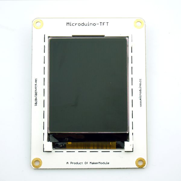
Microduino-TFT is the 1.8-inch 128*160 colorful display module based on ST7735, adopting SPI interface and 3.3V power supply.
Contents[hide]Features
Specification
Document
Development
The two libraries must be used together. Application
PurchaseHistoryPicturesVideo |


