Difference between revisions of "Microduino-Shield UNO"
From Microduino Wiki
(→Features) |
(→Application) |
||
| (6 intermediate revisions by 2 users not shown) | |||
| Line 4: | Line 4: | ||
| | | | ||
[[file:Microduino-Uno-ks.jpg|400px|thumb|right|Microduino-Uno]] | [[file:Microduino-Uno-ks.jpg|400px|thumb|right|Microduino-Uno]] | ||
| − | Microduino-Uno is an extension board based on official Arduino board, you can use it just like Arduino with Microduino | + | Microduino-Uno is an extension board based on the official Arduino board, you can use it just like Arduino with Microduino-USBTTL and Microduino Core modules. |
|- | |- | ||
| | | | ||
==Features== | ==Features== | ||
| − | *Compatible with the pin of Arduino Uno | + | *Compatible with the pin of Arduino Uno. |
| − | *Wide-voltage DC power input (8 ~ 35V) supportable | + | *Wide-voltage DC power input (8 ~ 35V) supportable. |
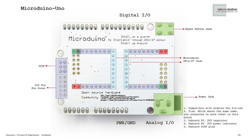
| − | *The 2. | + | *The 2.45mm (0.1 inch) pin pitch offers the base for Microduino modules and pins with the same name are connected to the base, making it easy for debugging; |
| − | *Uniform Microduino interface standard and rich peripheral modules | + | *Uniform Microduino interface standard and rich peripheral modules make it easy to connect with other modules and sensors meeting Microduino interface standard. |
==Specifications== | ==Specifications== | ||
| Line 17: | Line 17: | ||
*5V and 3.3V regulated power; | *5V and 3.3V regulated power; | ||
*LED indicator connected to D13 digit I/O port and lightened up with high electrical level; | *LED indicator connected to D13 digit I/O port and lightened up with high electrical level; | ||
| − | Onboard reset button; | + | *Onboard reset button; |
| − | *With serial | + | *With serial port(RX1, TX1), I2C(SCL, SDA), power(5V, 3.3V)and ground pin added; |
*Onboard ICSP pin; | *Onboard ICSP pin; | ||
*Two Microduino UPIN27 bases interconnected to the board. | *Two Microduino UPIN27 bases interconnected to the board. | ||
| Line 30: | Line 30: | ||
===Main Components=== | ===Main Components=== | ||
| − | *Switching | + | *Switching Chip: LM2674 '''[[File:LM2674.pdf]]''' |
| − | *LDO regulator | + | *LDO regulator chip: ASM1117 '''[[File:AMS1117-3.3.pdf]]''' |
| − | *Wound Chip Power | + | *Wound Chip Power Inductor: RWPA4018S '''[[File:RWPA4018S.pdf]]''' |
| − | *Schottky | + | *Schottky diode: SOD123 '''[[File:SOD-123.pdf]]''' |
==Development== | ==Development== | ||
| Line 40: | Line 40: | ||
==Application== | ==Application== | ||
You can download the program that Microduino provides to test the LED connected to D13 I/O port: | You can download the program that Microduino provides to test the LED connected to D13 I/O port: | ||
| − | + | *Prepared Hardware:Microduino FT232R, Microduino Core and Microduino UNO; | |
| − | *Prepared Hardware:Microduino FT232R, Microduino Core and Microduino | + | *Prepared Software:Microduino provides testing program(Arduino part)and Arduino IDE(version 1.0 and higher); |
| − | *Prepared Software:Microduino provides testing program(Arduino part)and Arduino IDE(version 1.0 and | ||
*Open Arduino IDE's Blink test program, choose the board "Microduino Core (Atmega328P@16M,5V)" and download directly. After finishing download,you can see the onboard LED flashes one time per second; | *Open Arduino IDE's Blink test program, choose the board "Microduino Core (Atmega328P@16M,5V)" and download directly. After finishing download,you can see the onboard LED flashes one time per second; | ||
Latest revision as of 10:46, 24 August 2016
| Language: | English • 中文 |
|---|
|
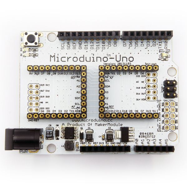
Microduino-Uno is an extension board based on the official Arduino board, you can use it just like Arduino with Microduino-USBTTL and Microduino Core modules. |
ContentsFeatures
Specifications
DocumentEagle PCB File:Microduino-UNO.zip Main Components
DevelopmentMicroduino-Uno is capable of having a fast and flexible connection and extension with other modules and sensors in accord with Microduino interface standard. ApplicationYou can download the program that Microduino provides to test the LED connected to D13 I/O port:
Pictures |


