Difference between revisions of "MCookie-WiFi"
(→Features) |
(→Images) |
||
| (22 intermediate revisions by 3 users not shown) | |||
| Line 4: | Line 4: | ||
| | | | ||
[[file:mCookie-8266-rect.jpg|400px|thumb|right|mCookie-WiFi]] | [[file:mCookie-8266-rect.jpg|400px|thumb|right|mCookie-WiFi]] | ||
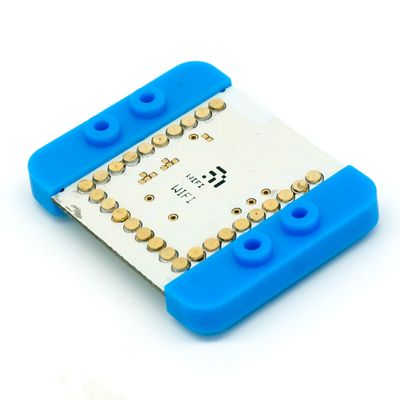
| − | mCookie-WiFi is WIFI communication module, which can connect other WIFI devices and communicate with CoreUSB via serial port. | + | mCookie-WiFi is WIFI communication module, which can connect other WIFI devices and communicate with [[MCookie-CoreUSB|mCookie CoreUSB]] via serial port. |
| − | + | [[MCookie-Core|mCookie Core]] cannot reach 115200 baud rate for serial communication and therefore won't work with the WiFi module. | |
| + | |||
| + | [[MCookie-Core+|mCookie Core+]] is supported, but see [[MCookie-WiFi#Core+_Issue|'''Core+ issue with WiFi module''']]. | ||
| + | |||
| + | =Features= | ||
*Serial communication. | *Serial communication. | ||
| − | *Accessible for the | + | *Accessible for the internet. |
*Small, stackable and economic. | *Small, stackable and economic. | ||
| − | + | =Specification= | |
| − | *Way of communication: Serial port transmission with the default serial port | + | *Way of communication: Serial port transmission with the default serial port D0(RX) and D1(TX). |
| − | *Power supply: +3.3VDC 50mA | + | *Power supply: +3.3VDC 50mA. |
| − | *Status indicator | + | *Status indicator. |
| − | + | =Common AT Instruction= | |
*All AT instructions are ended with "\r\n ". | *All AT instructions are ended with "\r\n ". | ||
| Line 32: | Line 36: | ||
***0: Use AL-LINK | ***0: Use AL-LINK | ||
***1: Use ESP-TOUCH | ***1: Use ESP-TOUCH | ||
| − | + | ***2: Use AIR-KISS | |
**AT+CWSMARTSTOP Stop smart connection | **AT+CWSMARTSTOP Stop smart connection | ||
| Line 48: | Line 52: | ||
**AT+CIPCLOSE=5 Close multi-connection | **AT+CIPCLOSE=5 Close multi-connection | ||
| − | **AT+CIPMUX=1 Start multi-connection | + | **AT+CIPMUX=1 Start multi-connection |
| − | + | =Document= | |
Support AT instruction configuration/contro: | Support AT instruction configuration/contro: | ||
'''[[File:ESP8266_WiFi_Module_Quick_Start_Guide_v_1.0.4.pdf]]''' | '''[[File:ESP8266_WiFi_Module_Quick_Start_Guide_v_1.0.4.pdf]]''' | ||
| − | + | =Development= | |
| − | + | ==Program== | |
[[File:ESP8266TestV1.zip]] | [[File:ESP8266TestV1.zip]] | ||
| Line 63: | Line 67: | ||
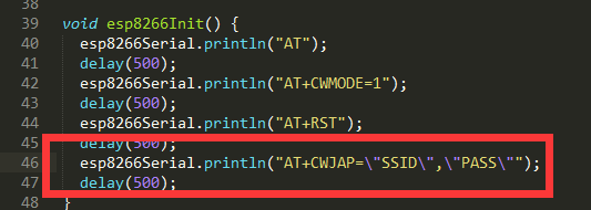
[[File:ESP8266ChangePass.png|thumb|600px|center]] | [[File:ESP8266ChangePass.png|thumb|600px|center]] | ||
| − | + | ==Download Program== | |
**Stacke mCookie-WiFi and mCookie-CoreUSB, plug USB cable into mCookie-CoreUSB on one side and connect computer USB socket on the other side. Then, start Arduino IDE, copy the program above to IDE, select Microduino-CoreUSB in (tools) -> (Board) and choose the right serial number in (tools) -> (Serial). After that, please click button (√) on the top left of IDE and compile the program. Burn the program to the board after compiling by clicking button (->); | **Stacke mCookie-WiFi and mCookie-CoreUSB, plug USB cable into mCookie-CoreUSB on one side and connect computer USB socket on the other side. Then, start Arduino IDE, copy the program above to IDE, select Microduino-CoreUSB in (tools) -> (Board) and choose the right serial number in (tools) -> (Serial). After that, please click button (√) on the top left of IDE and compile the program. Burn the program to the board after compiling by clicking button (->); | ||
*Open serial monitor and set "\r\n " and "115200 baud " | *Open serial monitor and set "\r\n " and "115200 baud " | ||
| Line 77: | Line 81: | ||
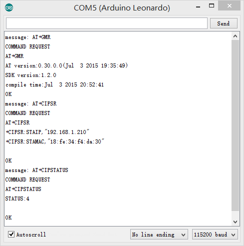
[[File:ESP8266WiF-AT.png|600px|center|thumb|AT]] | [[File:ESP8266WiF-AT.png|600px|center|thumb|AT]] | ||
| − | + | ==IDE Tests Program == | |
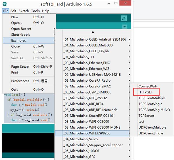
You can adopt HTTPGET program of _03_microduino_WiFi_ESP8266 from Microduino IDE example for testing. [[File:ESP8266-exampleCode.jpg|thumb|600px|center]] | You can adopt HTTPGET program of _03_microduino_WiFi_ESP8266 from Microduino IDE example for testing. [[File:ESP8266-exampleCode.jpg|thumb|600px|center]] | ||
| Line 83: | Line 87: | ||
Change your WIFI password in the code where there are SSID(WIFI name) and password setting. | Change your WIFI password in the code where there are SSID(WIFI name) and password setting. | ||
| − | + | ==Download Program == | |
| − | + | *Stack Microduino-WiFi(ESP) with Microduino-Core+ and Microduino-USBttl, plug USB cable into mCookie-CoreUSB on one side and connect computer USB socket on the other side. Then, start Arduino IDE, copy the program above to IDE, select Microduino-CoreUSB in (tools) -> (Board) and choose the right serial number in (tools) -> (Serial). After that, please click button (√) on the top left of IDE and compile the program. Burn the program to the board after compiliing by clicking button (->) | |
* Open serial monitor and set "\r\n " and "115200 baud " | * Open serial monitor and set "\r\n " and "115200 baud " | ||
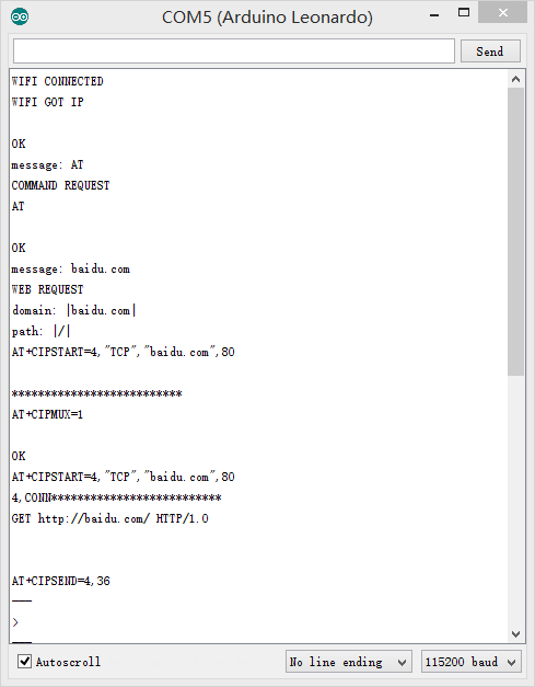
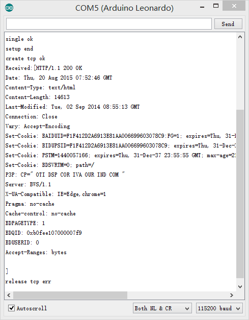
*Firstly, you'll see notice of successful WIFI connection. | *Firstly, you'll see notice of successful WIFI connection. | ||
*If you see content description, it means you have visited "www.baidu.com". [[File:ESP8266WiFi-exampleCode1.png|600px|center|thumb|Serial]] | *If you see content description, it means you have visited "www.baidu.com". [[File:ESP8266WiFi-exampleCode1.png|600px|center|thumb|Serial]] | ||
| − | + | =Pin Description= | |
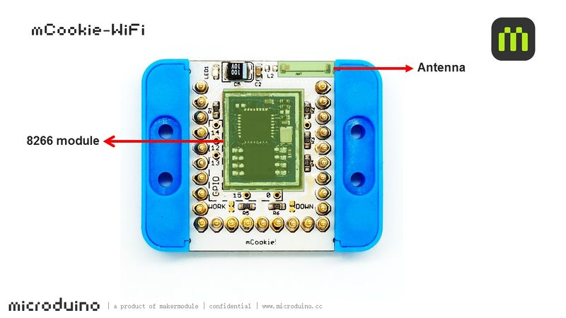
| − | + | Note: Images of the WiFi module are of an old revision. | |
:[[file:mCookie-WiFi-1Big2.jpg|800px|thumb|center|mCookie-WiFi]] | :[[file:mCookie-WiFi-1Big2.jpg|800px|thumb|center|mCookie-WiFi]] | ||
<br style="clear: left"/> | <br style="clear: left"/> | ||
| Line 96: | Line 100: | ||
<br style="clear: left"/> | <br style="clear: left"/> | ||
| − | + | =Project= | |
'''Related Projects: ''' | '''Related Projects: ''' | ||
[[WiFi Weatherstation]] | [[WiFi Weatherstation]] | ||
| − | == | + | =FAQ = |
| + | ==Core+ Issue== | ||
| + | <blockquote>I can't get the Core+ and WiFi module to work with the example codes!</blockquote> | ||
| + | mCookie modules and Microduino modules uses 27 pins. The pins are layed out in a '''"U"''' shape. In the mCookie Series, they are the 27 springy pins on the stackable modules. The pins each have various functions such as some provide power such as ground and power, or provide analog and / or digital input and output. Furthermore, some pins are used for serial communication. Serial communication is a type of communication used to communicate between different devices such as in mCookie between the core modules and communication modules (WiFi, Bluetooth, etc). There may be an issue with some early mCookie WiFi modules being shipped to communicate over pins 0 & 1 in 302 Expert Kits. | ||
| + | |||
| + | *Pin 0 & 1 are used to program a Core+ module. | ||
| + | *Pin 0 & 1 are used to debug (over serial port) a Core+ module. | ||
| + | *Pin 0 & 1 may be used by the WiFi module to communicate with the Core+ module. If the WiFi module is hardwired to use Pin 0 & 1. | ||
| + | |||
| + | This create a conflict of overlapping pins usage. The WiFi module will interfere with programming and debugging a Core+ module since both use the same Pin 0 & 1 for communication. | ||
| + | |||
| + | *Un-stacking the WiFi module will make the Core+ programmable. | ||
| + | *Debugging a Core+ module with WiFi using Pin 0 & 1 is not possible since there will be interference. | ||
| + | |||
| + | Although it is possible to use the Core+ and WiFi module in this configuration. It isn't particular easy to debug (since there is no serial monitor) and the constant un-stacking and re-stacking of the WiFi module to enable programming a Core+ module. | ||
| + | The solution to fix the overlapping and interference issue will be to rewire the WiFi module to use Pins 2 & 3 to communicate with a Core+ module. This will eliminate the programming and debugging issue. | ||
| + | |||
| + | Note: | ||
| + | *Pin 0 & 1 is referred to '''Serial''' in Core+ | ||
| + | *Pin 2 & 3 is referred to '''Serial1''' in Core+ | ||
| + | |||
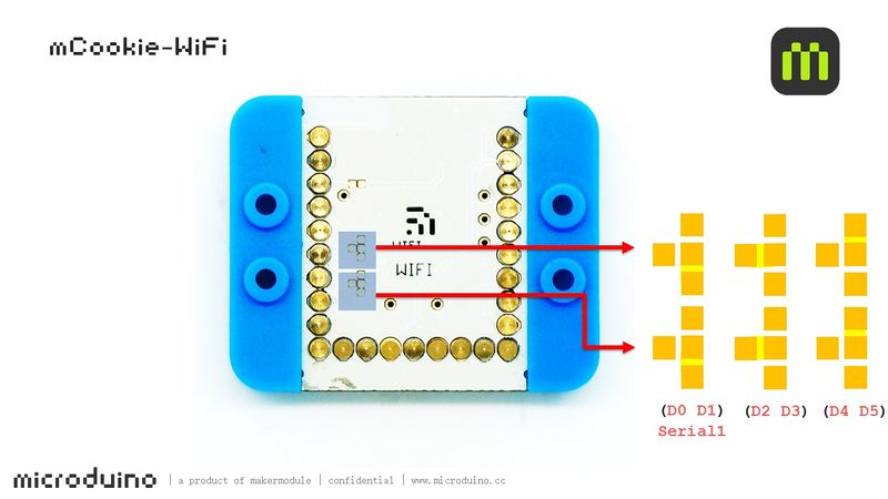
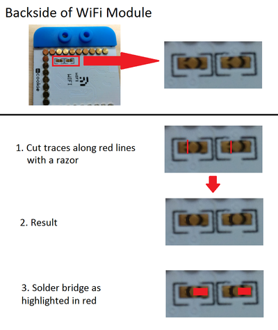
| + | This can be accomplished following the image below. It requires the use of a razor blade to cut two traces and connecting two pads with a soldering iron. Please proceed with caution with attempting this modification. As, done incorrectly can permanently damage the WiFi module. After the modification, the WiFi module will communicate with a Core+ module over Pins 2 & 3. And a Core+ module will continue to use Pins 0 & 1 for programming and debugging. Thus, removing the pin overlap interference issue. | ||
| + | |||
| + | [[file:WiFi_Modification.png|400px|center|thumb]] | ||
| − | == | + | =Images= |
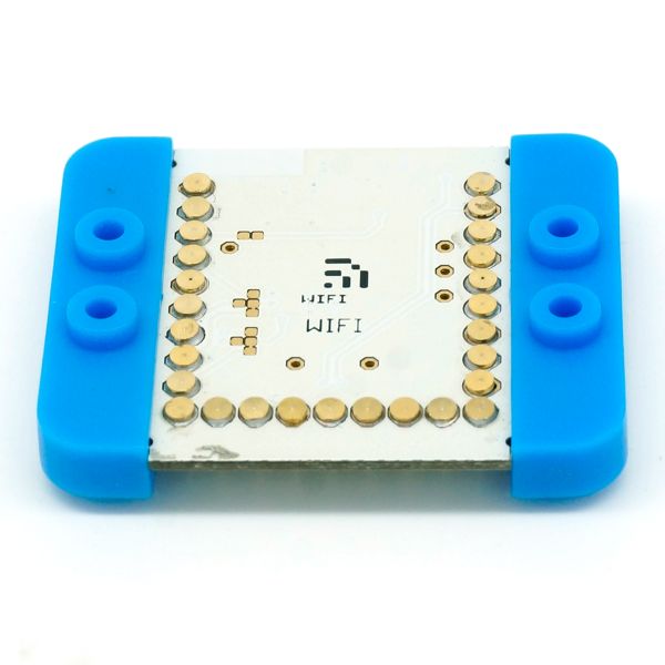
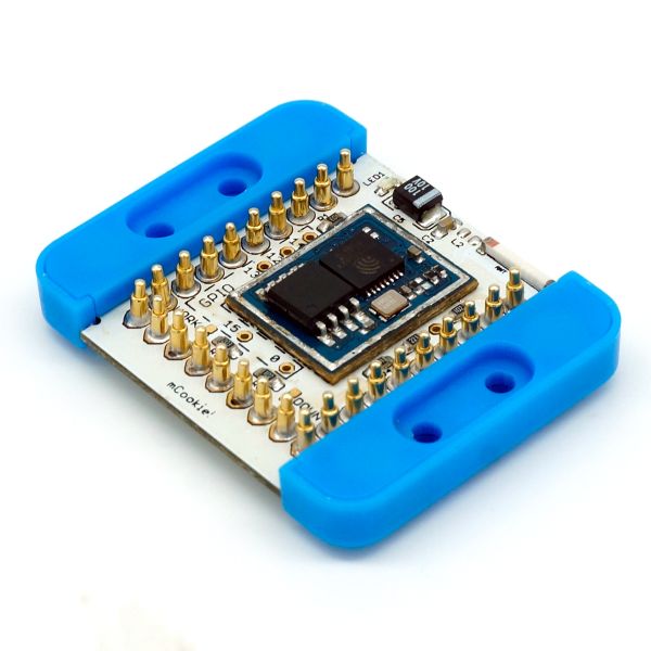
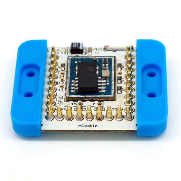
| + | Note: Images of the WiFi module are of an old revision. | ||
[[file:mCookie-WiFi-t1.jpg|thumb|600px|center]] | [[file:mCookie-WiFi-t1.jpg|thumb|600px|center]] | ||
[[file:mCookie-WiFi-b1.jpg|thumb|600px|center]] | [[file:mCookie-WiFi-b1.jpg|thumb|600px|center]] | ||
Latest revision as of 22:10, 29 March 2017
| Language: | English • 中文 |
|---|
|
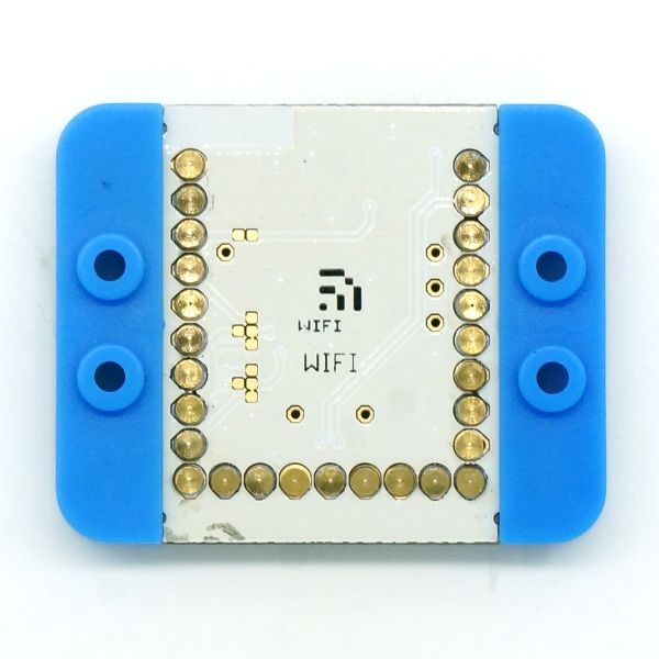
mCookie-WiFi is WIFI communication module, which can connect other WIFI devices and communicate with mCookie CoreUSB via serial port. mCookie Core cannot reach 115200 baud rate for serial communication and therefore won't work with the WiFi module. mCookie Core+ is supported, but see Core+ issue with WiFi module. ContentsFeatures
Specification
Common AT Instruction
DocumentSupport AT instruction configuration/contro: File:ESP8266 WiFi Module Quick Start Guide v 1.0.4.pdf DevelopmentProgramChange your WIFI password in the code where there are SSID(WIFI name) and password setting. Download Program
Such as:
IDE Tests ProgramYou can adopt HTTPGET program of _03_microduino_WiFi_ESP8266 from Microduino IDE example for testing.Change your WIFI password in the code where there are SSID(WIFI name) and password setting. Download Program
Pin DescriptionNote: Images of the WiFi module are of an old revision.
ProjectRelated Projects: WiFi Weatherstation FAQCore+ IssueI can't get the Core+ and WiFi module to work with the example codes! mCookie modules and Microduino modules uses 27 pins. The pins are layed out in a "U" shape. In the mCookie Series, they are the 27 springy pins on the stackable modules. The pins each have various functions such as some provide power such as ground and power, or provide analog and / or digital input and output. Furthermore, some pins are used for serial communication. Serial communication is a type of communication used to communicate between different devices such as in mCookie between the core modules and communication modules (WiFi, Bluetooth, etc). There may be an issue with some early mCookie WiFi modules being shipped to communicate over pins 0 & 1 in 302 Expert Kits.
This create a conflict of overlapping pins usage. The WiFi module will interfere with programming and debugging a Core+ module since both use the same Pin 0 & 1 for communication.
Although it is possible to use the Core+ and WiFi module in this configuration. It isn't particular easy to debug (since there is no serial monitor) and the constant un-stacking and re-stacking of the WiFi module to enable programming a Core+ module. The solution to fix the overlapping and interference issue will be to rewire the WiFi module to use Pins 2 & 3 to communicate with a Core+ module. This will eliminate the programming and debugging issue. Note:
This can be accomplished following the image below. It requires the use of a razor blade to cut two traces and connecting two pads with a soldering iron. Please proceed with caution with attempting this modification. As, done incorrectly can permanently damage the WiFi module. After the modification, the WiFi module will communicate with a Core+ module over Pins 2 & 3. And a Core+ module will continue to use Pins 0 & 1 for programming and debugging. Thus, removing the pin overlap interference issue. ImagesNote: Images of the WiFi module are of an old revision. |
