Difference between revisions of "Bluetooth Light"
(Created page with "{{Language| Bluetooth Light}} {| style="width: 800px;" |- | ==Overview== Here we can control the color and brightness of a light by App Android. When the phone is not connecte...") |
|||
| (One intermediate revision by one other user not shown) | |||
| Line 31: | Line 31: | ||
==Preparation== | ==Preparation== | ||
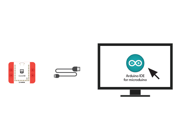
| − | *Setup | + | *Setup 1: Use a USB cable to connect the CoreUSB and the PC/Mac, the open Arduino IDE. |
[[Image:CoreUSB_Ble_pc.jpg|600px|center]] | [[Image:CoreUSB_Ble_pc.jpg|600px|center]] | ||
| − | *Setup | + | *Setup 2: |
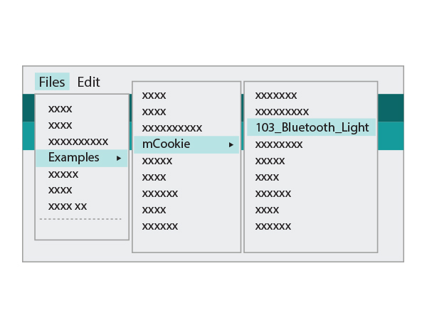
Click Files > Examples > mCookie > _103_BLE_Light, and load the program. Or download: | Click Files > Examples > mCookie > _103_BLE_Light, and load the program. Or download: | ||
[[File:_103_BLE_Light.jpg|600px|center]] | [[File:_103_BLE_Light.jpg|600px|center]] | ||
| − | * Setup | + | * Setup 3: Select the right board and COM port for program download. |
==Program Description== | ==Program Description== | ||
*Here the Bluetooth adopts serial communication. For mCookie-CoreUSB, it uses '''Serial1'''. So we define serial port service. | *Here the Bluetooth adopts serial communication. For mCookie-CoreUSB, it uses '''Serial1'''. So we define serial port service. | ||
| Line 59: | Line 59: | ||
Adafruit_NeoPixel strip = Adafruit_NeoPixel(6, A0, NEO_GRB + NEO_KHZ800); | Adafruit_NeoPixel strip = Adafruit_NeoPixel(6, A0, NEO_GRB + NEO_KHZ800); | ||
</source> | </source> | ||
| − | * | + | *"ble()" function is used to receive and analyze data sent from the phone: |
<source lang="cpp"> | <source lang="cpp"> | ||
sscanf((char *)strstr((char *)buffer, "C:"), "C:%d,%d,%d,%d", &sta[0], &sta[1], &sta[2], &sta[3]); | sscanf((char *)strstr((char *)buffer, "C:"), "C:%d,%d,%d,%d", &sta[0], &sta[1], &sta[2], &sta[3]); | ||
| Line 90: | Line 90: | ||
} | } | ||
</source> | </source> | ||
| − | * | + | *"rainbowCycle(w, R, G, B, x);" Function Using Description: Users can change the color as you like. |
| − | ** | + | **w: Delay time of the color gradual change. |
| − | ** | + | **R, G, B : Three primary colors. |
| − | ** | + | **x: "0" indicates the brightness changes from weak to strong; "1" indicates the brightness changes from strong to weak. |
==Hardware Buildup== | ==Hardware Buildup== | ||
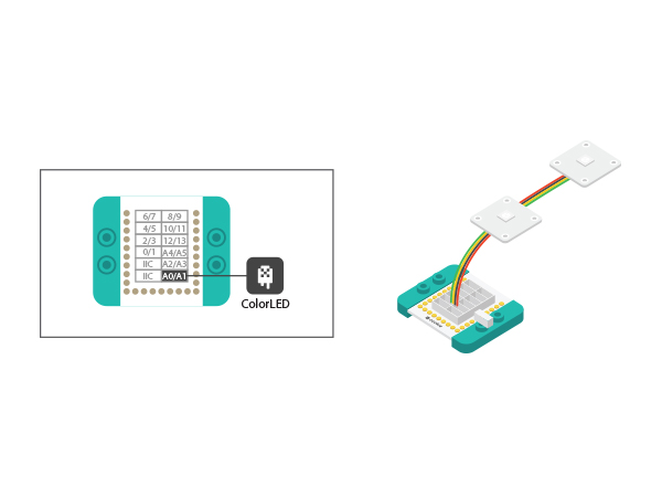
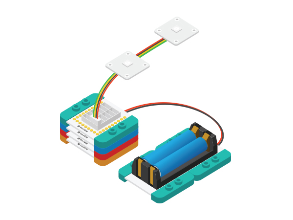
| − | *Setup | + | *Setup 1: Since the program code control adopts A0, you can connect the LED light to the Hub's A0 interface. Users can also customize the interface here. |
[[File:CoreUSB_Ble_steup1.jpg|600px|center]] | [[File:CoreUSB_Ble_steup1.jpg|600px|center]] | ||
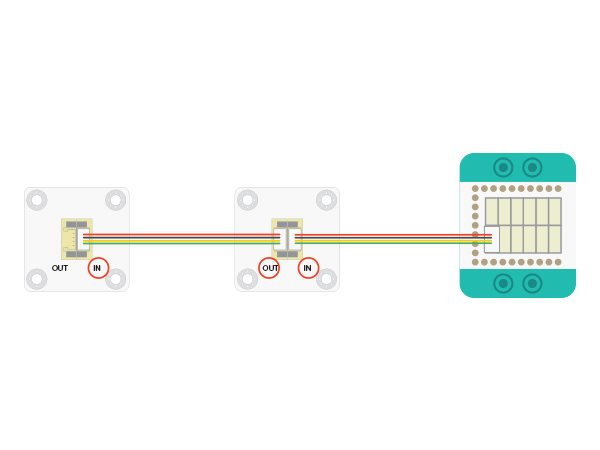
The connection method of the LED light can refer to the picture below. Please be noted of the connection order, which connect from LED's IN interface to OUT. | The connection method of the LED light can refer to the picture below. Please be noted of the connection order, which connect from LED's IN interface to OUT. | ||
[[File:CoreUSB_Ble_steup11.jpg|600px|center]] | [[File:CoreUSB_Ble_steup11.jpg|600px|center]] | ||
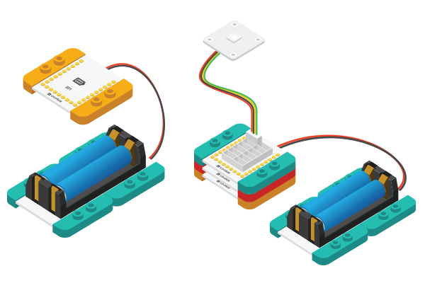
| − | *Setup | + | *Setup 2: Connect the activated battery box and the BM module. |
[[File:CoreUSB_Ble_steup2.jpg|600px|center]] | [[File:CoreUSB_Ble_steup2.jpg|600px|center]] | ||
| − | *Setup | + | *Setup 3: Then, stack all modules together without considering order. Congratulations! You've finished the circuit buildup. |
[[File:CoreUSB_Ble_steup3.jpg|600px|center]] | [[File:CoreUSB_Ble_steup3.jpg|600px|center]] | ||
==APP Debugging== | ==APP Debugging== | ||
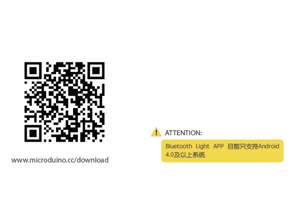
| − | *Setup | + | *Setup 1: Scan the two-dimensional code on the left and download Bluetooth Light App. |
[[File:app_Ble_steup1.jpg|600px|center]] | [[File:app_Ble_steup1.jpg|600px|center]] | ||
| − | *Setup | + | ios Source download link:[https://github.com/zidong0822/MLight2 LightBlue App] |
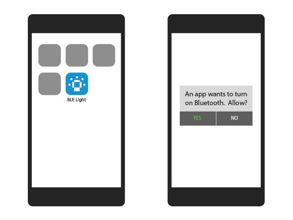
| + | *Setup 2: Open the App after the download and installation. If the Bluetooth is disconnected, the system will pop up a notice. | ||
[[File:app_Ble_steup2.jpg|600px|center]] | [[File:app_Ble_steup2.jpg|600px|center]] | ||
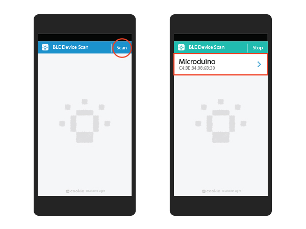
| − | *Setup | + | *Setup 3: Click Scan and the phone will start searching Bluetooth devices and display them below; Select the Microduino device. |
[[File:app_Ble_steup3.jpg|600px|center]] | [[File:app_Ble_steup3.jpg|600px|center]] | ||
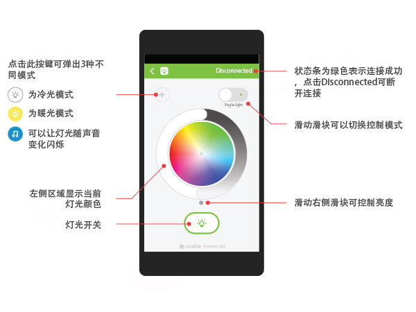
| − | *Setup | + | *Setup 4: After the connection, you can use your phone to control LED lights. |
[[File:app_Ble_steup4.jpg|600px|center]] | [[File:app_Ble_steup4.jpg|600px|center]] | ||
Latest revision as of 06:55, 30 September 2016
| Language: | English • 中文 |
|---|
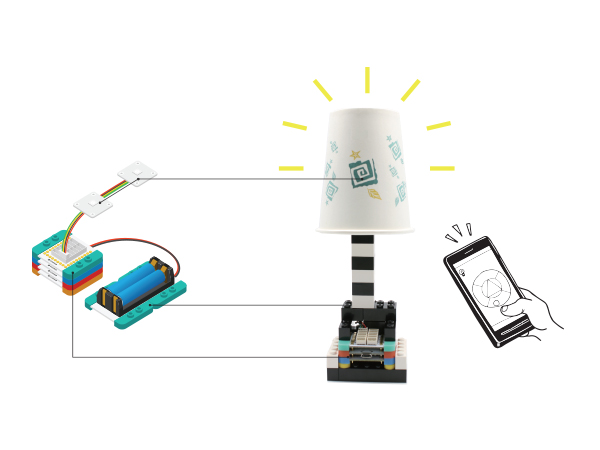
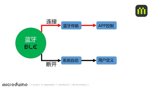
ContentsOverviewHere we can control the color and brightness of a light by App Android. When the phone is not connected to the Bluetooth, the light can automatically change color. While after the phone is connected, you can change the light to any color through the phone. PrincipleThe system can tell whether the mobile phone Bluetooth and mCookie-BT are connected or not. When connected, the system receives the data from the App to the mobile phone mCookie-BT, and analysis it out so as to control the color of the lamp. When the Bluetooth is disconnected, the system enters the pre-set color changing mode. Unless there is a Bluetooth connection, otherwise it'll enter the cycle mode.
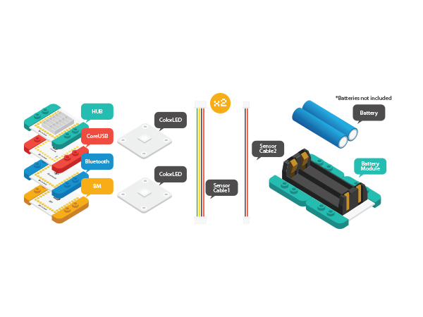
Equipment
Preparation
Click Files > Examples > mCookie > _103_BLE_Light, and load the program. Or download:
Program Description
#define my_Serial Serial1
my_Serial.begin(9600);
#define PIXEL_PIN    A0    // Digital IO pin connected to the NeoPixels.
#define PIXEL_COUNT  6

Adafruit_NeoPixel strip = Adafruit_NeoPixel(PIXEL_COUNT, PIXEL_PIN, NEO_GRB + NEO_KHZ800);
Adafruit_NeoPixel strip = Adafruit_NeoPixel(6, A0, NEO_GRB + NEO_KHZ800);
sscanf((char *)strstr((char *)buffer, "C:"), "C:%d,%d,%d,%d", &sta[0], &sta[1], &sta[2], &sta[3]);Transmission protocol analyzed from the code: " C:%d,%d,%d,%d " and assign value of the four analyzed data "%d " to sta[0], sta[1], sta[2] and sta[3], three of which are the color values of the R, G and B. The last value is the control mode selection.
    if (-1 == sta[3]) {
      colorSet(strip.Color(sta[0], sta[1], sta[2]));
    }
    else if ((0 <= sta[3]) && (sta[3] < PIXEL_COUNT)) {
      colorSet(strip.Color(sta[0], sta[1], sta[2]), sta[3]);
    }
If the value of sta[3] is -1, then all lights connected display the same color. That color is combined by " sta[0], sta[1], sta[2]",namely, the color selected on the phone. Otherwise, these six lights can also be controlled separately.
  if (c == '\n')
    {
      color_en = true;
      safe_ms = millis();
    }
  if (millis() - safe_ms > 3000)//Users can change the time. The unit of "3,000" is "ms".
  {
    safe_ms = millis();
    color_en = false;
  }
Hardware Buildup
The connection method of the LED light can refer to the picture below. Please be noted of the connection order, which connect from LED's IN interface to OUT.
APP Debugging
ios Source download link:LightBlue App
Video |
