Difference between revisions of "Microduino-Module CoreRF"
(Created page with "{{Language|Microduino-CoreRF}} {| style="width: 800px;" |- | 400px|thumb|right|Microduino-CoreUSB Microduino CoreRF is an AVR core board with 802.15.4 Wi...") |
|||
| (12 intermediate revisions by 2 users not shown) | |||
| Line 3: | Line 3: | ||
|- | |- | ||
| | | | ||
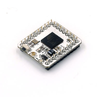
| − | [[File: | + | [[File:1DSC01831.JPG|400px|thumb|right|Microduino-CoreRF]] |
Microduino CoreRF is an AVR core board with 802.15.4 Wireless Protocol integrated. It supports any wireless modules based on 802.15.4 Protocol, including Zigbee, MAC/6LoWPAN and RF4CE. | Microduino CoreRF is an AVR core board with 802.15.4 Wireless Protocol integrated. It supports any wireless modules based on 802.15.4 Protocol, including Zigbee, MAC/6LoWPAN and RF4CE. | ||
| Line 18: | Line 18: | ||
{|class="wikitable" | {|class="wikitable" | ||
|- | |- | ||
| − | | | + | |Power supply||3.3 V |
|- | |- | ||
|Flash||128 KB | |Flash||128 KB | ||
| Line 32: | Line 32: | ||
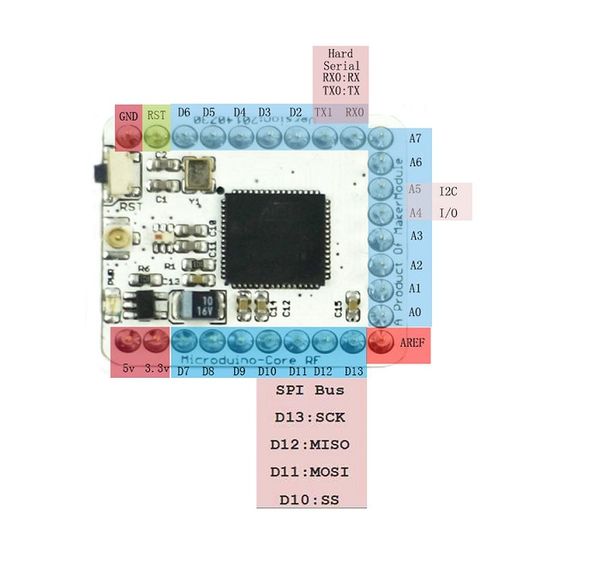
* 22 digital I/O ports (6 of them supports ADC): | * 22 digital I/O ports (6 of them supports ADC): | ||
*2-channel hard serial port: | *2-channel hard serial port: | ||
| − | ** | + | **UART0_RX: D0 |
| − | ** | + | **UART0_TX: D1 |
| − | ** | + | **UART1_RX: D2 |
| − | ** | + | **UART1_TX: D3 |
*Support 7-channel PWM: | *Support 7-channel PWM: | ||
| − | ** | + | **D4, D5, D6, D7, D8, D9, D10 |
*6-channel external interrupt: | *6-channel external interrupt: | ||
**Interrupt0 (pin SCL) | **Interrupt0 (pin SCL) | ||
| Line 46: | Line 46: | ||
**Interrupt5 (pin D6) | **Interrupt5 (pin D6) | ||
* 10 Analog I/O ports: | * 10 Analog I/O ports: | ||
| − | ** In the module, it is marked with A0,A1,A2,A3,A6,A7,D8(A8),D9(A9),D3(A10) and D4(A11). | + | ** In the module, it is marked with A0, A1, A2, A3, A6, A7, D8(A8), D9(A9), D3(A10) and D4(A11). |
** Each offers 10-bit resolution(0-1024). The measurement range of the analog voltage is from GND to VCC by default. | ** Each offers 10-bit resolution(0-1024). The measurement range of the analog voltage is from GND to VCC by default. | ||
** For more information, please refer to '''[http://www.arduino.cc/en/Reference/AnalogRead analogRead()]'''. | ** For more information, please refer to '''[http://www.arduino.cc/en/Reference/AnalogRead analogRead()]'''. | ||
*Support 1-channel SPI: | *Support 1-channel SPI: | ||
| − | **In the module, it's marked with D13(SCK),D12(MISO),D11(MOSI),D10(SS) | + | **In the module, it's marked with D13(SCK), D12(MISO), D11(MOSI), D10(SS). |
*Support 1-channel IIC: | *Support 1-channel IIC: | ||
| − | **In the module, it is marked with SDA(D18),SCL(D19) | + | **In the module, it is marked with SDA(D18), SCL(D19). |
| Line 128: | Line 128: | ||
==Document== | ==Document== | ||
*Eagle PCB | *Eagle PCB | ||
| − | Schematic of CoreRF: 【'''[[media:Microduino-Core RF. | + | Schematic of CoreRF: 【'''[[media:Microduino-Core RF.png |CoreRF schematic diagram]]'''】 |
| Line 136: | Line 136: | ||
==Development== | ==Development== | ||
| − | * 1.For uploading programs to Microduino CoreRF, you'll need to use '''[[Microduino-USBTTL]]''' | + | * 1.For uploading programs to Microduino CoreRF, you'll need to use '''[[Microduino-USBTTL]]''' module. |
* 2.For IDE setup and driver installation, please refer to below: | * 2.For IDE setup and driver installation, please refer to below: | ||
**'''[[Microduino Getting start]]''' | **'''[[Microduino Getting start]]''' | ||
| Line 142: | Line 142: | ||
* Burn Microduino BootLoader | * Burn Microduino BootLoader | ||
**If the BootLoader fails, you need to use Arduino UNO or the other Microduino board to burn bootloader for the broken Microduino. | **If the BootLoader fails, you need to use Arduino UNO or the other Microduino board to burn bootloader for the broken Microduino. | ||
| − | **Users can refer to the tutorial: '''[[ | + | **Users can refer to the tutorial: '''[[Do you know how to use Arduino UNO to program bootloader to Microduino-Core?]]'''. |
==Project== | ==Project== | ||
Latest revision as of 09:43, 9 September 2016
| Language: | English • 中文 |
|---|
|
Microduino CoreRF is an AVR core board with 802.15.4 Wireless Protocol integrated. It supports any wireless modules based on 802.15.4 Protocol, including Zigbee, MAC/6LoWPAN and RF4CE. Contents[hide]Features
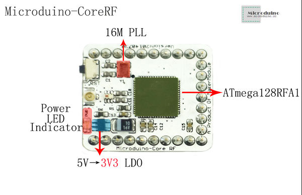
SpecificationAdopt ATmega128RFA1 core chip
Document
Schematic of CoreRF: 【CoreRF schematic diagram】
ATmega128RFA1: http://www.atmel.com/zh/cn/devices/ATMEGA128RFA1.aspx?tab=documents Development
ProjectMicroduino-Quadcopter Tutorial TestUse program examples in ZigduinoRadio library to test. void loop()
{
if (Serial.available())
{
ZigduinoRadio.beginTransmission();
Serial.println();
Serial.print("Tx: ");
while(Serial.available())
{
char c = Serial.read();
Serial.write(c);
ZigduinoRadio.write(c);
}
Serial.println();
ZigduinoRadio.endTransmission();
}
if (ZigduinoRadio.available())
{
Serial.println();
Serial.print("Rx: ");
while(ZigduinoRadio.available())
Serial.write(ZigduinoRadio.read());
Serial.println();
Serial.print("LQI: ");
Serial.print(ZigduinoRadio.getLqi(), 10);
Serial.print(", RSSI: ");
Serial.print(ZigduinoRadio.getLastRssi(), 10);
Serial.print(" dBm, ED: ");
Serial.print(ZigduinoRadio.getLastEd(), 10);
Serial.println("dBm");
}
delay(100);
}
void errHandle(radio_error_t err)
{
Serial.println();
Serial.print("Error: ");
Serial.print((uint8_t)err, 10);
Serial.println();
}
void onXmitDone(radio_tx_done_t x)
{
Serial.println();
Serial.print("TxDone: ");
Serial.print((uint8_t)x, 10);
Serial.println();
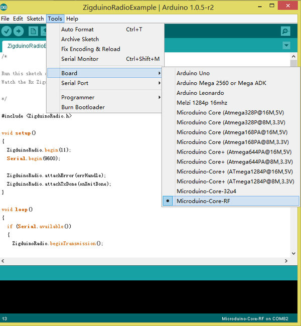
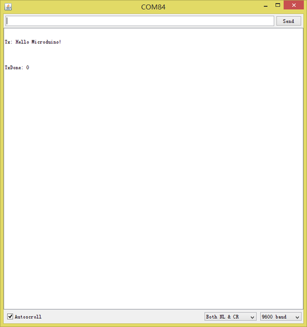
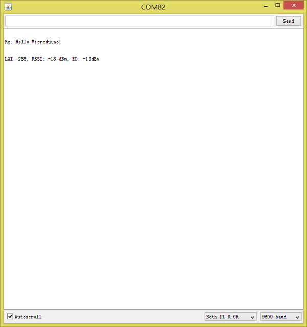
}This example realizes wireless serial transmission function. Since the CoreRF adopts serial port download, you need firstly stack a Microduino-USBTTL on it: Choose Microduino CoreRF as the board card Open the serial monitor after uploading programs to the two Core-RF modules, input " Hello Microduino!", click "Send" and you'll get the following result: By here, we've completed the test. FAQPurchaseHistoryPicture
Video |
