|
|
| (16 intermediate revisions by 3 users not shown) |
| Line 69: |
Line 69: |
| | *There are various kinds of Robot cars, such as robot car of tracking, barrier, Bluetooth control, which with different functions and need to adopt different sensors. | | *There are various kinds of Robot cars, such as robot car of tracking, barrier, Bluetooth control, which with different functions and need to adopt different sensors. |
| | *However, all those Robot cars are basically controlled in the same way, that is, moving in four directions. | | *However, all those Robot cars are basically controlled in the same way, that is, moving in four directions. |
| − |
| |
| | *Here we adopt two-wheel drive structure. By control the rotation of two wheels, we can achieve moving forward and backward, or spinning. Of course, it needs auxiliary wheel to keep balance. | | *Here we adopt two-wheel drive structure. By control the rotation of two wheels, we can achieve moving forward and backward, or spinning. Of course, it needs auxiliary wheel to keep balance. |
| | *This car has a simple structure, including wheels, body and control system. | | *This car has a simple structure, including wheels, body and control system. |
| Line 98: |
Line 97: |
| | | | |
| | ==Installation== | | ==Installation== |
| | + | |
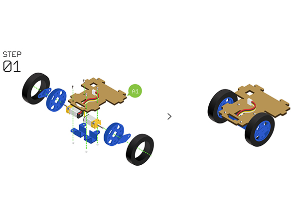
| | *'''Step1''': | | *'''Step1''': |
| | **Adopt '''Motor fixation base''' to fixate the two '''N20 gear motors ''' on the '''Structure-A1'''. | | **Adopt '''Motor fixation base''' to fixate the two '''N20 gear motors ''' on the '''Structure-A1'''. |
| | **Assemble the '''Wheels''', '''tyres''' and '''Couplings''', then install them with the fixated '''N20 gear motor'''. | | **Assemble the '''Wheels''', '''tyres''' and '''Couplings''', then install them with the fixated '''N20 gear motor'''. |
| | + | |
| | [[File:Cubestep1.jpg||600px|center]] | | [[File:Cubestep1.jpg||600px|center]] |
| | + | |
| | + | |
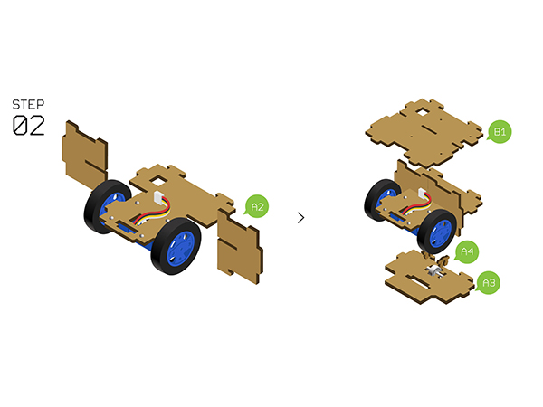
| | *'''Step2''': | | *'''Step2''': |
| | *Insert '''Structure-A2''' into the slot of the two sides of '''Structure-A1'''. | | *Insert '''Structure-A2''' into the slot of the two sides of '''Structure-A1'''. |
| Line 107: |
Line 110: |
| | *Prepare '''Structure-A3''' and '''Structure-B1''' from up to down as the picture shows below. | | *Prepare '''Structure-A3''' and '''Structure-B1''' from up to down as the picture shows below. |
| | [[File:Cubestep2.jpg||600px|center]] | | [[File:Cubestep2.jpg||600px|center]] |
| | + | |
| | + | |
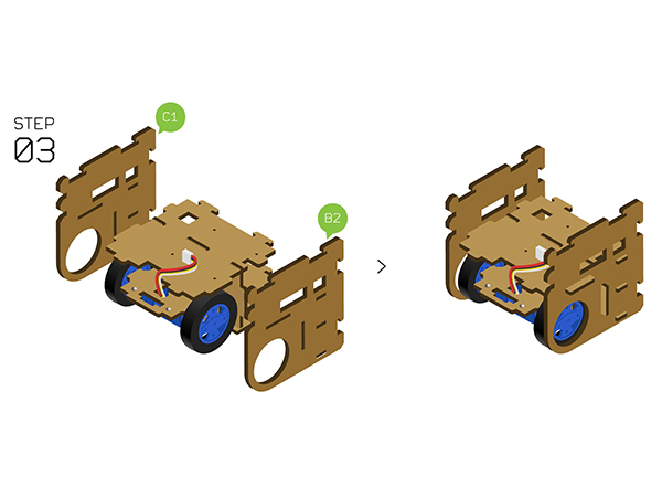
| | *'''Step3''': | | *'''Step3''': |
| | *Fixate the'''Structure-B2''' and '''Structure-C1''' on the two sides. | | *Fixate the'''Structure-B2''' and '''Structure-C1''' on the two sides. |
| | [[File:Cubestep3.jpg||600px|center]] | | [[File:Cubestep3.jpg||600px|center]] |
| | + | |
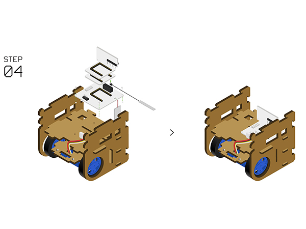
| | *'''Step4''': | | *'''Step4''': |
| | *Stack the following modules on the'''[[Microduino-Robot]]'''. | | *Stack the following modules on the'''[[Microduino-Robot]]'''. |
| Line 120: |
Line 126: |
| | *Fixate '''[[Microduino-Robot]]''' on'''Structure-B1''' with screws. | | *Fixate '''[[Microduino-Robot]]''' on'''Structure-B1''' with screws. |
| | [[File:Cubestep4.jpg||600px|center]] | | [[File:Cubestep4.jpg||600px|center]] |
| | + | |
| | + | |
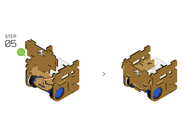
| | *'''Step5''': | | *'''Step5''': |
| | *Fixate '''Auxiliary wheels''' on '''Structure-C2''' with two '''Structure-C3'''. | | *Fixate '''Auxiliary wheels''' on '''Structure-C2''' with two '''Structure-C3'''. |
| | *Insert the '''Structure-C2''' to the front side. | | *Insert the '''Structure-C2''' to the front side. |
| | [[File:Cubestep5.jpg||600px|center]] | | [[File:Cubestep5.jpg||600px|center]] |
| | + | |
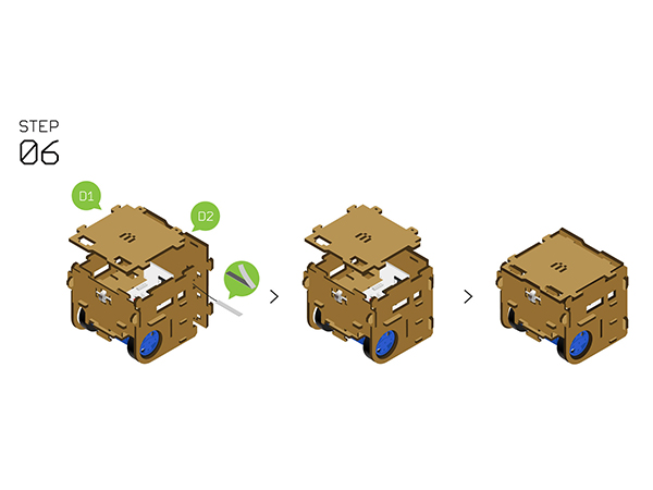
| | *'''Step6''': | | *'''Step6''': |
| | *Insert'''Structure-D2''' to the back side and stick the antenna. | | *Insert'''Structure-D2''' to the back side and stick the antenna. |
| Line 143: |
Line 152: |
| | | | |
| | ===Guide for Bluetooth Control=== | | ===Guide for Bluetooth Control=== |
| − | *Bluetooth control APP download: [[File:MTank.rar|MTank.]] | + | *First of all, download remote control APP(Android): '''[[File:mTank.rar]]''' |
| | + | *Confirm that the version of your phone is above Android 4.3 and the Bluetooth is open. |
| | + | *Search the Bluetooth device named '''"Microduino"''', and connect to it. |
| | + | *Then you can control it remotely by APP. |
| | + | *For details, please refer to '''[[mRobot]]''' |
| | | | |
| | ==Code Description== | | ==Code Description== |
Outline
- Project: Open Source Electric Drive Cube Robot
- Objective: To make a Cube Robot car
- Can be controlled by Joypad.
- Also can support Bluetooth APP control.
- Difficulty: Middle
- Time-consuming: 2-Hour
- Maker: PKJ
Bill of Material
Bill of Modules(Joypad mode)
Bill of Module(Bluetooth mode)
Other Material
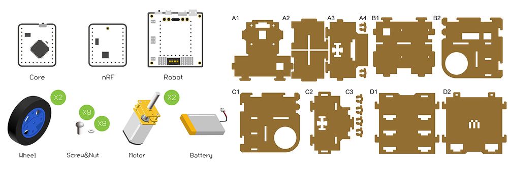
| Component |
Number |
Function
|
| Frame of the Robot car |
1 |
Body of the car
|
| Screw |
18 |
Fixation
|
| Nut |
8 |
Fixation
|
| Micro-USB cable |
1 |
Download program
|
| 47mm wheel+ motor fixing seat |
2 |
Car wheels
|
| N20DC speed-down motor |
2 |
Drive wheels
|
| 3.7V Li-ion battery |
1 |
Power supply
|
Principle of the Experiment
- There are various kinds of Robot cars, such as robot car of tracking, barrier, Bluetooth control, which with different functions and need to adopt different sensors.
- However, all those Robot cars are basically controlled in the same way, that is, moving in four directions.
- Here we adopt two-wheel drive structure. By control the rotation of two wheels, we can achieve moving forward and backward, or spinning. Of course, it needs auxiliary wheel to keep balance.
- This car has a simple structure, including wheels, body and control system.
- 1)The wheels adopt two speed-down motors with large torque, which can have PWM speed adjustment to make sure easy control.
- 2)The body of the car adopts wood with a size of 8cm*8cm*8cm.
- 3)The whole control system contains four parts:
- CPU
- Adopt Microduino-Core as the core. Just like the CPU of a computer, it can analyze and process complicated things.
- Wireless commmunciation
- Adopt Microduino-nRF24 wireless communication scheme with fast communication response and the control range of about 50m in the open area.
- Or adopt Microduino-BT wireless communication scheme, which can work with phone APP to directly control. The control range is about 20m in the open area.
- Motor control
- Adopt a group of built-in DC motor drive unit on the Microduino-Robot, and a unit can drive two motors.
- Power supply system
- Adopt a built-in sing-cell Li-ion battery management unit on the Microduino-Robot to manage charging and discharging function.
Program Download
Programming
- Stack Microduino-Core and Microduino-USBTTL together, then use the USB cable to connect the USBTTL module for program uploading.
- Note: Please upload programs before stacking all modules together.
- Open Arduino IDE for Microduino development environment. (For the buildup, please refer to: AVR Core:Getting started )
- Make sure the right board(Microduino-Core Atmega328P@16M,5V) and the relevant port number(COMX)
- Open the " Robot_Microduino.ino " program in the downloaded projects.
- Click "→" and upload the program to the development board.
Installation
- Step1:
- Adopt Motor fixation base to fixate the two N20 gear motors on the Structure-A1.
- Assemble the Wheels, tyres and Couplings, then install them with the fixated N20 gear motor.
- Step2:
- Insert Structure-A2 into the slot of the two sides of Structure-A1.
- Use two Structure-A4 to fixate the bottom of Auxiliary wheel on the Structure-A3.
- Prepare Structure-A3 and Structure-B1 from up to down as the picture shows below.
- Step3:
- Fixate theStructure-B2 and Structure-C1 on the two sides.
- Step5:
- Fixate Auxiliary wheels on Structure-C2 with two Structure-C3.
- Insert the Structure-C2 to the front side.
- Step6:
- InsertStructure-D2 to the back side and stick the antenna.
- Put the Structure-D1 on the top and by here, congratulations! You just completed the installation.
Instructions of the Remote Control
- If stacking the nRF module and start, the system will enter the Joypad control mode by default, otherwise, it'll enter the Bluetooth mode.
Guide for Joypad Control
- For the installation, you can refer to the following page: [1]
Guide for Bluetooth Control
- First of all, download remote control APP(Android): File:MTank.rar
- Confirm that the version of your phone is above Android 4.3 and the Bluetooth is open.
- Search the Bluetooth device named "Microduino", and connect to it.
- Then you can control it remotely by APP.
- For details, please refer to mRobot
Code Description
- Find the configuration file in " user_def.h ".
- The following codes can configure the channel under nRF mode, which needs to keep consistent with Joypad controller.
- For the Joypad's nRF mode channel configuraton, you can refer to: Channel Configuration of nRF Mode
#define NRF_CHANNEL 70 //nRF channel - The following codes can configure the throttle and the corresponding steering channel.
- For the corresponding channel, you can refer to: Channel/Operation Description
#define CHANNEL_THROTTLE  2 //Throttle channel
#define CHANNEL_STEERING 1 //Steering channel - The following codes can revise the speed ratio of the two wheels.
- The range is between -1 and 1.
- Set as -1, the maximum speed ratio, clockwise.
- Set as 1, the maximum speed ratio, anti-clockwise.
- If the car cannot go straightly, you should reduce the speed ratio of the lower wheel.
#define motor_fixL 1  //Speed correction (-1 to 1)
#define motor_fixR 1  // Speed correction (-1 to 1)
FAQ
- Q:How to choose Joypad mode or Bluetooth mode for this CUBE robot?
- A:You don't have to select manually but stack nRF24 module when power-on. The system will enter the Joypad mode by default, or it'll enter Bluetooth mode.
- Q:What type of battery does the CUBE robot support?
- A:It supports 3.7V 1S lithium battery.
- Q:How to connect the motors?
- A:You can connect the two motors to the A.A/A.B interfaces respectively.
- Q:Does my phone support Bluetooth control?
- A:It is supportable for phones of Android 4.3 or higher.
|
