Difference between revisions of "Open Source Electric Drive Cube Robot"
From Microduino Wiki
(→Installation) |
|||
| (12 intermediate revisions by 3 users not shown) | |||
| Line 69: | Line 69: | ||
*There are various kinds of Robot cars, such as robot car of tracking, barrier, Bluetooth control, which with different functions and need to adopt different sensors. | *There are various kinds of Robot cars, such as robot car of tracking, barrier, Bluetooth control, which with different functions and need to adopt different sensors. | ||
*However, all those Robot cars are basically controlled in the same way, that is, moving in four directions. | *However, all those Robot cars are basically controlled in the same way, that is, moving in four directions. | ||
| − | |||
*Here we adopt two-wheel drive structure. By control the rotation of two wheels, we can achieve moving forward and backward, or spinning. Of course, it needs auxiliary wheel to keep balance. | *Here we adopt two-wheel drive structure. By control the rotation of two wheels, we can achieve moving forward and backward, or spinning. Of course, it needs auxiliary wheel to keep balance. | ||
*This car has a simple structure, including wheels, body and control system. | *This car has a simple structure, including wheels, body and control system. | ||
| Line 102: | Line 101: | ||
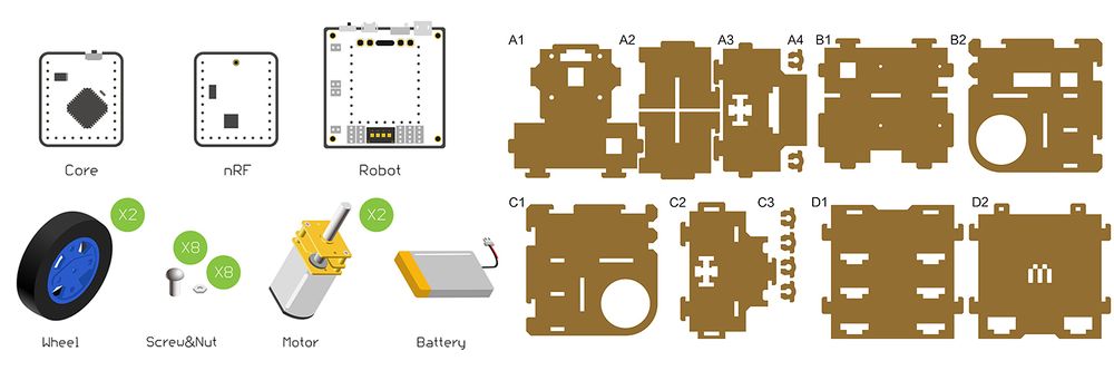
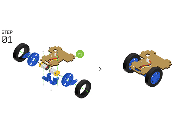
**Adopt '''Motor fixation base''' to fixate the two '''N20 gear motors ''' on the '''Structure-A1'''. | **Adopt '''Motor fixation base''' to fixate the two '''N20 gear motors ''' on the '''Structure-A1'''. | ||
**Assemble the '''Wheels''', '''tyres''' and '''Couplings''', then install them with the fixated '''N20 gear motor'''. | **Assemble the '''Wheels''', '''tyres''' and '''Couplings''', then install them with the fixated '''N20 gear motor'''. | ||
| − | [[File:Cubestep1.jpg||600px| | + | |
| + | [[File:Cubestep1.jpg||600px|center]] | ||
| + | |||
*'''Step2''': | *'''Step2''': | ||
| Line 108: | Line 109: | ||
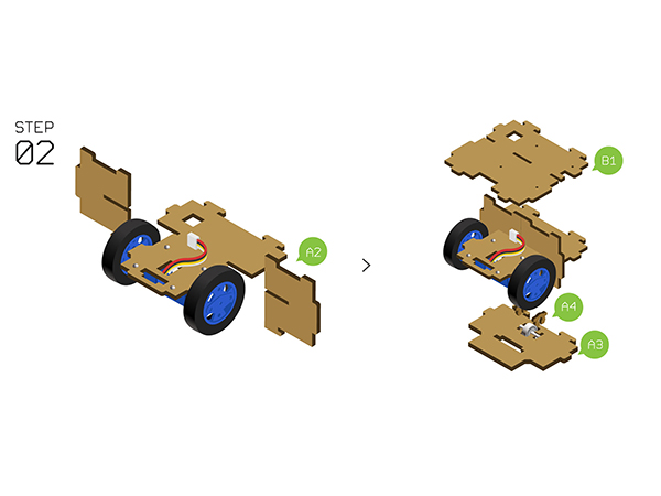
*Use two '''Structure-A4''' to fixate the bottom of '''Auxiliary wheel''' on the '''Structure-A3'''. | *Use two '''Structure-A4''' to fixate the bottom of '''Auxiliary wheel''' on the '''Structure-A3'''. | ||
*Prepare '''Structure-A3''' and '''Structure-B1''' from up to down as the picture shows below. | *Prepare '''Structure-A3''' and '''Structure-B1''' from up to down as the picture shows below. | ||
| − | [[File:Cubestep2.jpg||600px| | + | [[File:Cubestep2.jpg||600px|center]] |
| + | |||
*'''Step3''': | *'''Step3''': | ||
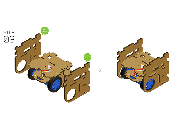
*Fixate the'''Structure-B2''' and '''Structure-C1''' on the two sides. | *Fixate the'''Structure-B2''' and '''Structure-C1''' on the two sides. | ||
| − | [[File:Cubestep3.jpg||600px| | + | [[File:Cubestep3.jpg||600px|center]] |
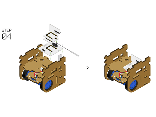
*'''Step4''': | *'''Step4''': | ||
| Line 123: | Line 125: | ||
*Connect two '''N20 gear motors''' to the A.A/A.B motor interfaces on the base of '''[[Microduino-Robot]]'''. | *Connect two '''N20 gear motors''' to the A.A/A.B motor interfaces on the base of '''[[Microduino-Robot]]'''. | ||
*Fixate '''[[Microduino-Robot]]''' on'''Structure-B1''' with screws. | *Fixate '''[[Microduino-Robot]]''' on'''Structure-B1''' with screws. | ||
| − | [[File:Cubestep4.jpg||600px| | + | [[File:Cubestep4.jpg||600px|center]] |
| + | |||
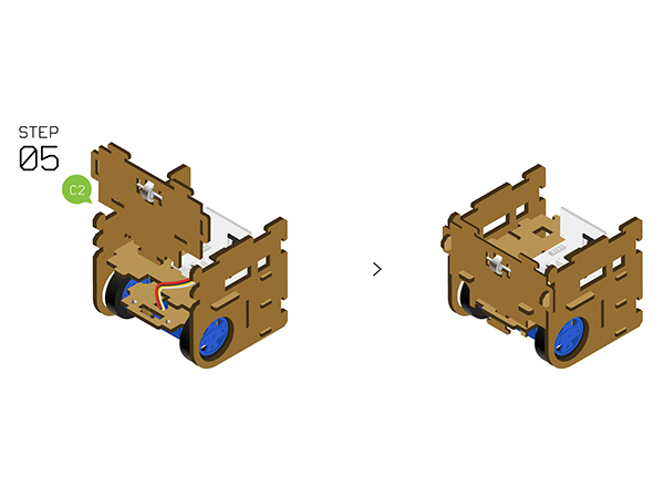
*'''Step5''': | *'''Step5''': | ||
*Fixate '''Auxiliary wheels''' on '''Structure-C2''' with two '''Structure-C3'''. | *Fixate '''Auxiliary wheels''' on '''Structure-C2''' with two '''Structure-C3'''. | ||
*Insert the '''Structure-C2''' to the front side. | *Insert the '''Structure-C2''' to the front side. | ||
| − | [[File:Cubestep5.jpg||600px| | + | [[File:Cubestep5.jpg||600px|center]] |
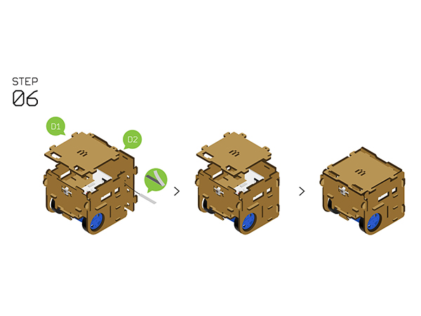
*'''Step6''': | *'''Step6''': | ||
*Insert'''Structure-D2''' to the back side and stick the antenna. | *Insert'''Structure-D2''' to the back side and stick the antenna. | ||
*Put the '''Structure-D1''' on the top and by here, congratulations! You just completed the installation. | *Put the '''Structure-D1''' on the top and by here, congratulations! You just completed the installation. | ||
| − | [[File:Cubestep6.jpg||600px| | + | [[File:Cubestep6.jpg||600px|center]] |
==Instructions of the Remote Control == | ==Instructions of the Remote Control == | ||
| Line 149: | Line 152: | ||
===Guide for Bluetooth Control=== | ===Guide for Bluetooth Control=== | ||
| − | * | + | *First of all, download remote control APP(Android): '''[[File:mTank.rar]]''' |
| + | *Confirm that the version of your phone is above Android 4.3 and the Bluetooth is open. | ||
| + | *Search the Bluetooth device named '''"Microduino"''', and connect to it. | ||
| + | *Then you can control it remotely by APP. | ||
| + | *For details, please refer to '''[[mRobot]]''' | ||
==Code Description== | ==Code Description== | ||
Latest revision as of 03:13, 30 March 2017
ContentsOutline
Bill of MaterialBill of Modules(Joypad mode)
Bill of Module(Bluetooth mode)
Other Material
Principle of the Experiment
Program Download
Programming
Installation
Instructions of the Remote Control
Guide for Joypad Control
Guide for Bluetooth Control
Code Description
#define NRF_CHANNEL 70 //nRF channel
#define CHANNEL_THROTTLE  2 //Throttle channel
#define CHANNEL_STEERING  1 //Steering channel
#define motor_fixL 1  //Speed correction (-1 to 1)
#define motor_fixR 1  // Speed correction (-1 to 1)
FAQ
|
