Difference between revisions of "MCookie-Base"
From Microduino Wiki
| Line 13: | Line 13: | ||
==Specification== | ==Specification== | ||
*[[Microduino-BM]] interface: | *[[Microduino-BM]] interface: | ||
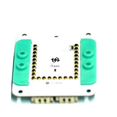
| − | **A 1.27-spacing | + | **A 1.27-spacing 4Pin interface, the one labeled("VUSB","SWI","BAT" and "GND"), through which be connected with [[Microduino-BM]]; |
**The interfaces playing a role of UPIN27 includes 5V, 3V3, and GND;A7 of BM can detect the analog voltage, and can judge the electricity quality of the battery through detecting the voltage of battery with mc. You mustn’t rely on the protection circuit to protect the battery, because the protection circuit is only working in extreme cases. | **The interfaces playing a role of UPIN27 includes 5V, 3V3, and GND;A7 of BM can detect the analog voltage, and can judge the electricity quality of the battery through detecting the voltage of battery with mc. You mustn’t rely on the protection circuit to protect the battery, because the protection circuit is only working in extreme cases. | ||
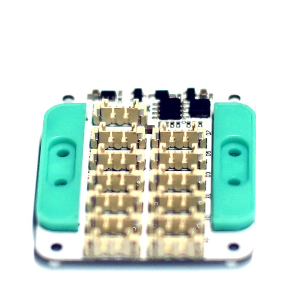
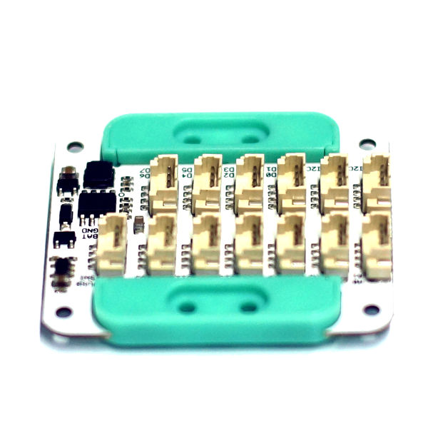
*Hub sensor interfaces: | *Hub sensor interfaces: | ||
Latest revision as of 03:36, 4 August 2017
|
ContentsFeatures
Specification
Description of pins File:MCookie-base.jpg pinout File:MCookie-base-2.jpg pinout Power Supply
DocumentsMain Components
Development
//Voltage detection pin, A7pin
#define PIN_bat A7  //BAT

//MCU working voltage, which need to be chosen according to the situation.
#define MCU_VOLTAGE 50
//#define MCU_VOLTAGE 33

#define _V_max 41   //4.2V
#define _V_min 35   //3.7V

#define _V_fix 0.2  //fix battery voltage
#define _V_math(Y) (_V_fix+((Y*analogRead(PIN_bat)/1023.0f)/(33.0f/(51.0f+33.0f))))

uint8_t batVoltage() {
  return constrain(_V_math(MCU_VOLTAGE), _V_min, _V_max);
}
Application
FAQHistoryGallery |


