Difference between revisions of "Lesson 12--Microduino "Light indicator""
(Created page with "{| style="width: 800px;" |- | ==Objective== In photoresistance experiment, The light is divided into two levels, strong or weak. This experiment will finish a light indictor u...") |
m (photo added) |
||
| (6 intermediate revisions by 4 users not shown) | |||
| Line 1: | Line 1: | ||
| + | {{Language|第十二课--Microduino_光照指示器}} | ||
{| style="width: 800px;" | {| style="width: 800px;" | ||
|- | |- | ||
| Line 13: | Line 14: | ||
**Breadboard one piece | **Breadboard one piece | ||
**Photoresistance one | **Photoresistance one | ||
| − | **LED Light-emitting diodes | + | **LED Light-emitting diodes four |
| − | **220Ω | + | **220Ω four |
**10k resistor one | **10k resistor one | ||
**USB Data cable one | **USB Data cable one | ||
| + | |||
| + | [[File:lesson11All.jpg|600px|center|thumb]] | ||
==Experimental schematic== | ==Experimental schematic== | ||
| − | [[File: | + | [[File:lesson12-schematic.jpg|600px|center|thumb]] |
The photoresistance's connection in contrast to the last time, the purpose is let you know the usage of photoresistance deeply. | The photoresistance's connection in contrast to the last time, the purpose is let you know the usage of photoresistance deeply. | ||
photoresistance directly connects to the power supply at one end, the other end through a resistance to connect GND . | photoresistance directly connects to the power supply at one end, the other end through a resistance to connect GND . | ||
| Line 66: | Line 69: | ||
==Result== | ==Result== | ||
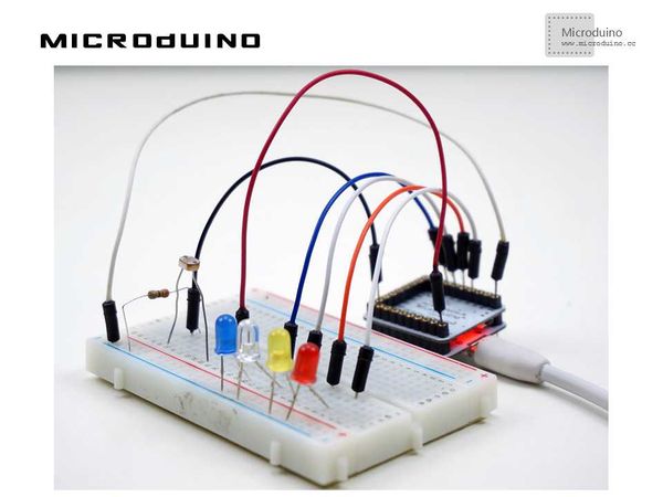
When the light is very weak, lower the seted minimum value, all the lights are off. With the increase of light, reach to a set level would light up an LED, to achieve the effect of instruction. Actually LED lamp has been flashing, because in order to make the light intensity is not a certain level, to put out the light of the level, directly after the lights out immediately, with no delay in the implementation process, as long as the grade, circulation processing, so it looks as if always on. | When the light is very weak, lower the seted minimum value, all the lights are off. With the increase of light, reach to a set level would light up an LED, to achieve the effect of instruction. Actually LED lamp has been flashing, because in order to make the light intensity is not a certain level, to put out the light of the level, directly after the lights out immediately, with no delay in the implementation process, as long as the grade, circulation processing, so it looks as if always on. | ||
| + | |||
| + | [[File:lesson11Result.jpg|600px|center|thumb]] | ||
| + | |||
| + | ==Video== | ||
| + | |||
| + | https://www.youtube.com/watch?v=U3aOOc4cxtI | ||
Latest revision as of 07:09, 3 July 2015
| Language: | English • 中文 |
|---|
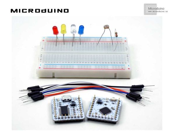
ObjectiveIn photoresistance experiment, The light is divided into two levels, strong or weak. This experiment will finish a light indictor using 4 LEDs and divides the light into 5 levels. Photoresistance receives the more light, and light up more LED to achieve the purpose of instruction. Equipment
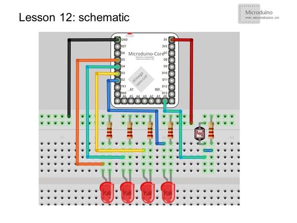
Experimental schematicThe photoresistance's connection in contrast to the last time, the purpose is let you know the usage of photoresistance deeply. photoresistance directly connects to the power supply at one end, the other end through a resistance to connect GND . The initial state is low, with the increase of light intensity voltage is higher and higher. Programvoid setup ()
{
Serial.begin(115200);
for(int i=2; i<=5;i++) //Set the I/O port 2 - 5 to output mode.
{
pinMode(i,OUTPUT);
}
}
void loop ()
{
int n =analogRead(A0); //Read the value of photoresistance
//Serial.println(n);
if (n>=100) //Judge the color hierarchy. You can djust the level values according to your own used environment, minimum is 0, and maximun is 1023.
{
digitalWrite(2,HIGH);
digitalWrite(2,LOW); //When no longer this level, the lights will go off
}
if(n>250)
{
digitalWrite(3,HIGH);
digitalWrite(3,LOW);
}
if(n>400)
{
digitalWrite(4,HIGH);
digitalWrite(4,LOW);
}
if(n>550)
{
digitalWrite(5,HIGH);
digitalWrite(5,LOW);
}
// delay(100);
}ResultWhen the light is very weak, lower the seted minimum value, all the lights are off. With the increase of light, reach to a set level would light up an LED, to achieve the effect of instruction. Actually LED lamp has been flashing, because in order to make the light intensity is not a certain level, to put out the light of the level, directly after the lights out immediately, with no delay in the implementation process, as long as the grade, circulation processing, so it looks as if always on. Video |


