Difference between revisions of "Lesson 8--Microduino Infrared Transmitting and Receiving"
(→Program) |
|||
| (2 intermediate revisions by 2 users not shown) | |||
| Line 15: | Line 15: | ||
**The infrared receiver one | **The infrared receiver one | ||
**Infrared transmitting tube one (Find it in old infrared remote controler) | **Infrared transmitting tube one (Find it in old infrared remote controler) | ||
| − | + | **Two resistors of 220 Ohm | |
'''The Infrared Receiver''' | '''The Infrared Receiver''' | ||
[[File:第八课-红外接收器.jpg|600px|center|thumb]] | [[File:第八课-红外接收器.jpg|600px|center|thumb]] | ||
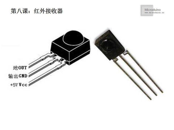
'''Brief introduction:''' | '''Brief introduction:''' | ||
| − | The infrared receiver is a kind of device which can receive the infrared signal and can independently from the infrared receiver to output signal | + | The infrared receiver is a kind of device which can receive the infrared signal and can independently from the infrared receiver to output signal compatible with TTL level signal. Its volume is the sama as an encapsulation triode, suitable for all kinds of infrared remote control and infrared data transmission. |
| − | '''The Infrared Receiver | + | '''The Infrared Receiver Features: ''' |
*Small size | *Small size | ||
| Line 36: | Line 36: | ||
| − | ''' | + | '''Note:''' |
1. Storage and use in the absence of any external pressure and influence the quality of the environment. | 1. Storage and use in the absence of any external pressure and influence the quality of the environment. | ||
| Line 54: | Line 54: | ||
[[File:第八课-红外发射管.jpg|600px|center|thumb]] | [[File:第八课-红外发射管.jpg|600px|center|thumb]] | ||
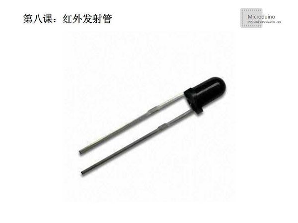
'''Brief introduction:''' | '''Brief introduction:''' | ||
| − | Infrared transmitting tube is composed of infrared | + | Infrared transmitting tube is composed of infrared LEDs, use material of high infrared radiation efficiency (commonly used gallium arsenide) to made PN junction, forward biased current injection to the PN to stimulate infrared light, the spectral power distribution as the center wavelength of 830 ~ 950 nm. |
Short for LED is Light Emitting Diode, performance is a positive temperature coefficient, the higher temperature with the greater current. the greater the size of the LED lamp power and current, but the forward current exceeds maximum value, the infrared lamp transmitted power will decline. | Short for LED is Light Emitting Diode, performance is a positive temperature coefficient, the higher temperature with the greater current. the greater the size of the LED lamp power and current, but the forward current exceeds maximum value, the infrared lamp transmitted power will decline. | ||
| − | '''How to identify the | + | '''How to identify the pin:''' |
Generally infrared transmitting tube has two pins, one is long, the other is short, like the LED diode. Long pin connects to the anode, short pin connects the cathode. | Generally infrared transmitting tube has two pins, one is long, the other is short, like the LED diode. Long pin connects to the anode, short pin connects the cathode. | ||
| − | |||
==Experiment 1 - Infrared Receive== | ==Experiment 1 - Infrared Receive== | ||
| Line 72: | Line 71: | ||
<source lang="cpp"> | <source lang="cpp"> | ||
| − | //This example comes from | + | //This example comes from infrared receive moudle's IRremote example |
/* | /* | ||
* IRremote: IRrecvDemo - demonstrates receiving IR codes with IRrecv | * IRremote: IRrecvDemo - demonstrates receiving IR codes with IRrecv | ||
| Line 104: | Line 103: | ||
==Debug== | ==Debug== | ||
| − | Step | + | Step 1: Download IRremote library |
[http://www.geek-workshop.com/forum.php?mod=attachment&aid=ODk2N3wyYmQ0YTJlYnwxMzkxODcwMDU5fDI4MTYzfDI0MzM=] | [http://www.geek-workshop.com/forum.php?mod=attachment&aid=ODk2N3wyYmQ0YTJlYnwxMzkxODcwMDU5fDI4MTYzfDI0MzM=] | ||
| − | Step | + | Step 2: Uncompress the library to libraries folder of Arduino IDE |
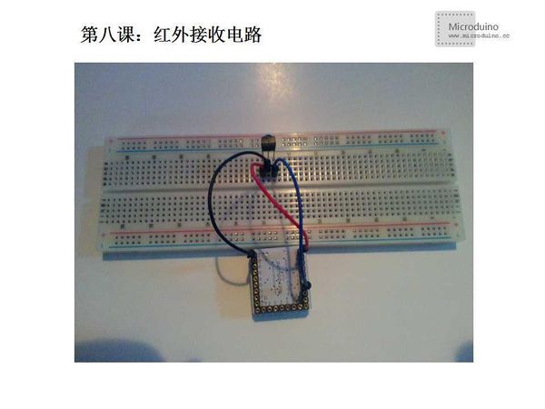
| − | Step | + | Step 3: Set up the circuit |
[[File:第八课-Microduino红外接收电路.jpg|600px|center|thumb]] | [[File:第八课-Microduino红外接收电路.jpg|600px|center|thumb]] | ||
| − | Step | + | Step 4: Open the program, compile it and download |
| − | Step | + | Step 5: Open the serial monitor, infrared remote control toward to the infrared receiver and press different button. |
==Result== | ==Result== | ||
| Line 147: | Line 146: | ||
pinMode(buttonPin, INPUT); | pinMode(buttonPin, INPUT); | ||
| − | digitalWrite(ledPin, HIGH); // | + | digitalWrite(ledPin, HIGH); // light LED(ObservE by mobile phone camera mode) |
delay(3000); // Wait for 3s | delay(3000); // Wait for 3s | ||
digitalWrite(ledPin, LOW); // the end of testing | digitalWrite(ledPin, LOW); // the end of testing | ||
| Line 172: | Line 171: | ||
==Debug== | ==Debug== | ||
| − | + | Step 1: Download IRremote library | |
[http://www.geek-workshop.com/forum.php?mod=attachment&aid=ODk2N3wyYmQ0YTJlYnwxMzkxODcwMDU5fDI4MTYzfDI0MzM=] | [http://www.geek-workshop.com/forum.php?mod=attachment&aid=ODk2N3wyYmQ0YTJlYnwxMzkxODcwMDU5fDI4MTYzfDI0MzM=] | ||
| − | Step | + | Step 2: Uncompress the library to libraries folder of Arduino IDE |
| − | Step | + | Step 3: Set up the circuit |
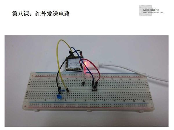
[[File:第八课-Microduino红外发送电路.jpg|600px|center|thumb]] | [[File:第八课-Microduino红外发送电路.jpg|600px|center|thumb]] | ||
| − | Step | + | Step 4: Open the program, compile it and download |
| − | Step | + | Step 5: Press the button, infrared transmitting tube will launch infrared coding, due to the infrared light invisible to the naked eye, but can be seen in the camera. |
==Result== | ==Result== | ||
| − | With a button to control whether to send infrared, press the | + | With a button to control whether to send infrared, press the button infrared tubes will send the infrared code that you set. |
==Video== | ==Video== | ||
| − | |||
| − | |||
Latest revision as of 08:03, 12 September 2016
| Language: | English • 中文 |
|---|
ContentsObjectiveThis tutorial will teach you how to collect TV infrared remote control code, and sends the recorded infrared code. Equipment
The Infrared Receiver Brief introduction: The infrared receiver is a kind of device which can receive the infrared signal and can independently from the infrared receiver to output signal compatible with TTL level signal. Its volume is the sama as an encapsulation triode, suitable for all kinds of infrared remote control and infrared data transmission. The Infrared Receiver Features:
1. The pulse signal output PORT, connect microcontroller IO port directly 2. GND connects to system GND 3. Vcc connects to system power (+5V)
1. Storage and use in the absence of any external pressure and influence the quality of the environment. 2. Storage and use of non-polluting gas or sea wind (salty) environment. 3. Storage and use in low temperature environment. 4. Under the specified conditions to welding the pin. After welding, do not apply force. 5. Do not wash the product, before use connect the operator and the ground wire with electrostatic belt. 6. Note infrared receiver receiving surface, contamination or wear will affect the reception, and do not touch the surface
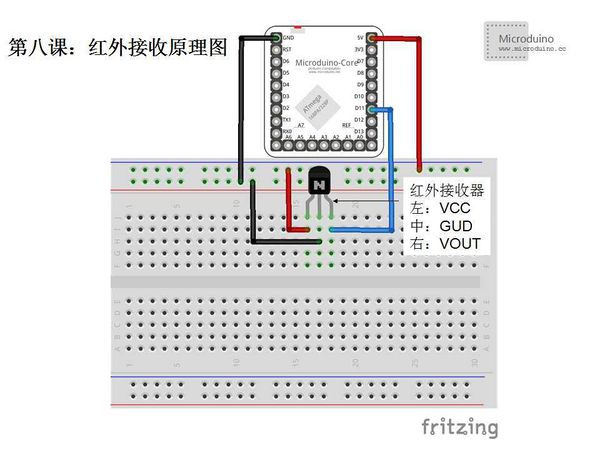
Brief introduction: Infrared transmitting tube is composed of infrared LEDs, use material of high infrared radiation efficiency (commonly used gallium arsenide) to made PN junction, forward biased current injection to the PN to stimulate infrared light, the spectral power distribution as the center wavelength of 830 ~ 950 nm. Short for LED is Light Emitting Diode, performance is a positive temperature coefficient, the higher temperature with the greater current. the greater the size of the LED lamp power and current, but the forward current exceeds maximum value, the infrared lamp transmitted power will decline. How to identify the pin: Generally infrared transmitting tube has two pins, one is long, the other is short, like the LED diode. Long pin connects to the anode, short pin connects the cathode. Experiment 1 - Infrared ReceiveSchematicProgramDownload program: https://github.com/Microduino/Microduino_Tutorials/tree/master/Microduino_Advanced/MicroduinoIRReceiver //This example comes from infrared receive moudle's IRremote example
/*
* IRremote: IRrecvDemo - demonstrates receiving IR codes with IRrecv
* An IR detector/demodulator must be connected to the input RECV_PIN.
* Version 0.1 July, 2009
* Copyright 2009 Ken Shirriff
* [url]http://arcfn.com[/url]
*/
#include <IRremote.h>
int RECV_PIN = 11;//Define the infrated receive pin
IRrecv irrecv(RECV_PIN);
decode_results results;
void setup()
{
Serial.begin(9600);
irrecv.enableIRIn(); // Initialize the infrated receiver
}
void loop() {
if (irrecv.decode(&results)) {
Serial.println(results.value, HEX);//Output the receive value using hexadecimal
Serial.println();//In order to watch the output increase a blank line
irrecv.resume(); //Receive next value
}
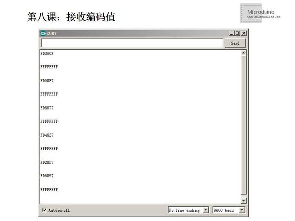
}DebugStep 1: Download IRremote library [1] Step 2: Uncompress the library to libraries folder of Arduino IDE Step 3: Set up the circuit Step 4: Open the program, compile it and download Step 5: Open the serial monitor, infrared remote control toward to the infrared receiver and press different button. ResultSee infrared codes of different keys.
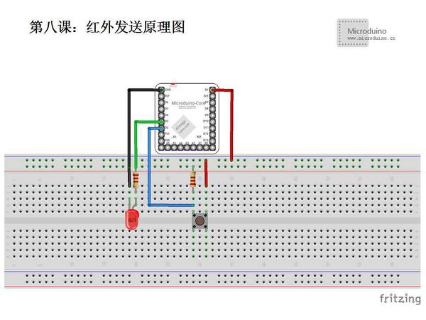
Experiment 2 - Infrared SendSchematicProgram#include <IRremote.h> // Invoke IRRemote library
IRsend irsend; // Define IRsend instance to send the infrared signal
// constants won't change. They're used here to
// set pin numbers:
const int buttonPin = 2; // the number of the pushbutton pin
const int ledPin = 3; // the number of the LED pin
// variables will change:
int buttonState = 0; // variable for reading the pushbutton status
void setup() {
// initialize the LED pin as an output:
pinMode(ledPin, OUTPUT);
// initialize the pushbutton pin as an input:
pinMode(buttonPin, INPUT);
digitalWrite(ledPin, HIGH); // light LED(ObservE by mobile phone camera mode)
delay(3000); // Wait for 3s
digitalWrite(ledPin, LOW); // the end of testing
}
void loop(){
// read the state of the pushbutton value:
buttonState = digitalRead(buttonPin);
// check if the pushbutton is pressed.
// if it is, the buttonState is HIGH:
if (buttonState == HIGH) {
Serial.print("SendIR: ");
irsend.sendNEC(0x234E817, 32); //9
}
else {
// turn LED off:
digitalWrite(ledPin, LOW);
}
}DebugStep 1: Download IRremote library [2] Step 2: Uncompress the library to libraries folder of Arduino IDE Step 3: Set up the circuit Step 4: Open the program, compile it and download Step 5: Press the button, infrared transmitting tube will launch infrared coding, due to the infrared light invisible to the naked eye, but can be seen in the camera. ResultWith a button to control whether to send infrared, press the button infrared tubes will send the infrared code that you set. Video |
