Difference between revisions of "Microduino-Module smartRF"
From Microduino Wiki
(→Development) |
|||
| (10 intermediate revisions by 4 users not shown) | |||
| Line 7: | Line 7: | ||
==Features== | ==Features== | ||
| − | * | + | *With highest working rate at 500KBPS, it supports 2-FSK, GFSK and MSK modulation; |
| − | * | + | *Capable of modifying baud rate, power, frequency and other related parameters by software; |
*High sensitivity (Under 1.2KBPS - 110dDm, 0.1% packet error rate); | *High sensitivity (Under 1.2KBPS - 110dDm, 0.1% packet error rate); | ||
*Low power consumption (1.2 KBaud,433 MHZ RX is 15 ma); | *Low power consumption (1.2 KBaud,433 MHZ RX is 15 ma); | ||
| − | *Built-in hardware CRC error detection and | + | *Built-in hardware CRC error detection and point-to-multipoint communication address control; |
| − | * | + | *With programmable and controllable power output,the maximum power is +10dBM; |
| − | * | + | *It owns wireless wake up function and supports low power electromagnetic wave activation function; |
==Specification== | ==Specification== | ||
*Low working voltage: 1.9 ~ 3.6V; | *Low working voltage: 1.9 ~ 3.6V; | ||
*Support 315/433/868/915MHZ ISM frequency band; | *Support 315/433/868/915MHZ ISM frequency band; | ||
| − | *Support 2- | + | *Support 2-FSK, GFSK and MSK modulation; |
*Lowest working rate is 1.2 KBPS, up to 500 KBPS; | *Lowest working rate is 1.2 KBPS, up to 500 KBPS; | ||
*Separate 64 byte RX and TX FIFO buffer; | *Separate 64 byte RX and TX FIFO buffer; | ||
| − | * | + | *Capable of meeting the requirements of multipoint communication and frequency hopping communication with 125 optional work channels; |
*Support RSSI strong and weak signal detection and carrier listening function; | *Support RSSI strong and weak signal detection and carrier listening function; | ||
| Line 55: | Line 55: | ||
==Application== | ==Application== | ||
| − | You can download the test program that Microduino | + | You can download the test program that Microduino offers, and use the Microduino-OLED module to test Microduino-smartRF. |
| − | *Prepared | + | *Prepared Hardware: Microduino FT232R, Microduino Core and Microduino-smartRF; |
| − | *Prepared | + | *Prepared Software: Microduino's test program (Arduino), Arduino IDE (upper to 1.0 release); |
| − | *Two Microduino | + | *Two Microduino-Core modules. |
| − | **ceshi_SMARTRF_T is the | + | By Microduino-smartRF communication test, the host machine sends the runtime to the auxiliary machine, which will be displayed on the OLED ; |
| − | ** | + | **ceshi_SMARTRF_T is the program sent by the host machine and ceshi_SMARTRF_R is the program sent by the auxiliary machine; |
| − | **Use the IDE to open the test program and | + | **The host machine needs Microduino-Core and Microduino-smartRF modules and the auxiliary machine needs Microduino-Core, Microduino-smartRF and MIcroduino-OLED as well as Microduino FT232R used to download program; |
| − | **After | + | **Use the IDE to open the test program and then upload the program to the host and auxiliary machine respectively; |
| − | **Restart | + | **After the upload, "Rec. pack #xx" will be displayed on OlED, and "xx" is the time that is sent from the host machine; |
| + | **Restart the host machine and start timing from zero, the data of the auxiliary machine will be also updated at the same time. | ||
| − | == | + | ==FAQ== |
| + | *Do you have module to support CC2511 or CC2500? | ||
| + | **So far we don't have this module. | ||
| + | |||
| + | ==Buy== | ||
==History== | ==History== | ||
Latest revision as of 04:25, 4 August 2017
| Language: | English • 中文 |
|---|
|
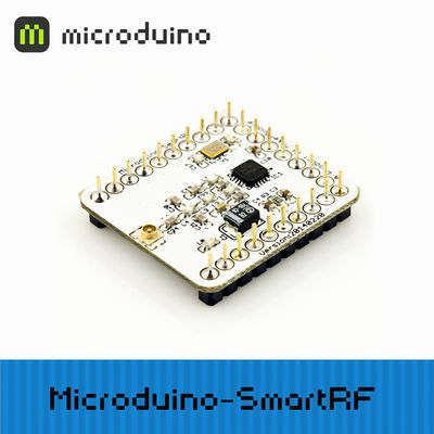
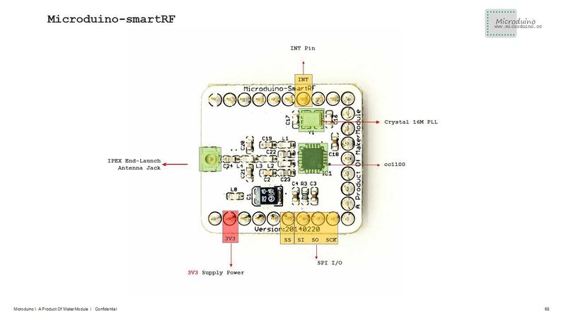
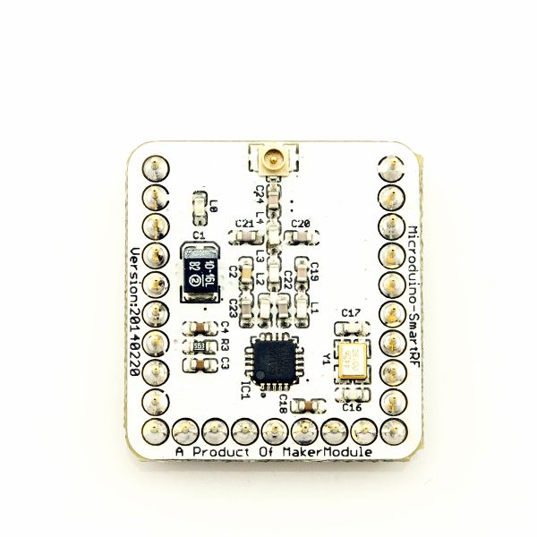
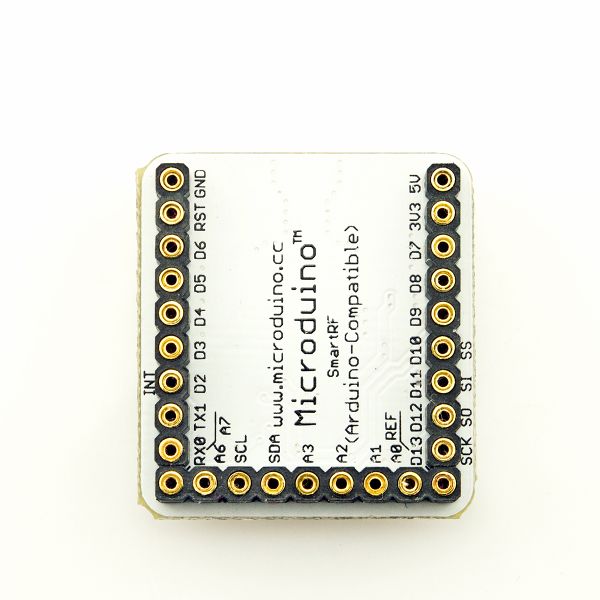
Microduino smartRF uses the latest high-performance CC1101 wireless communication chip, which can be widely applied to various short distance wireless communication field ContentsFeatures
Specification
DocumentEagle PCB download: Main chips
DevelopmentApplication library downlaod: https://github.com/Microduino/Microduino_Tutorials/tree/master/Microduino_Libraries/_03_Microduino_SmartRF_CC1101 Test program download: https://github.com/Microduino/Microduino_Tutorials/tree/master/Microduino_Texting/Microduino_SMARTRF ApplicationYou can download the test program that Microduino offers, and use the Microduino-OLED module to test Microduino-smartRF.
By Microduino-smartRF communication test, the host machine sends the runtime to the auxiliary machine, which will be displayed on the OLED ;
FAQ
BuyHistoryPictureFrontBackVideo |


