Difference between revisions of "DC Motor Control"
(Created page with "{| style="width: 800px;" |- | ==Objective== The course will show you how to use “Processing” to control the speed of the DC motor. ==Equipment== *'''Microduino-Core...") |
|||
| (One intermediate revision by one other user not shown) | |||
| Line 4: | Line 4: | ||
==Objective== | ==Objective== | ||
| − | The course will show you how to use | + | The course will show you how to use "Processing" to control the speed of the DC motor. |
==Equipment== | ==Equipment== | ||
| Line 33: | Line 33: | ||
==Debugging== | ==Debugging== | ||
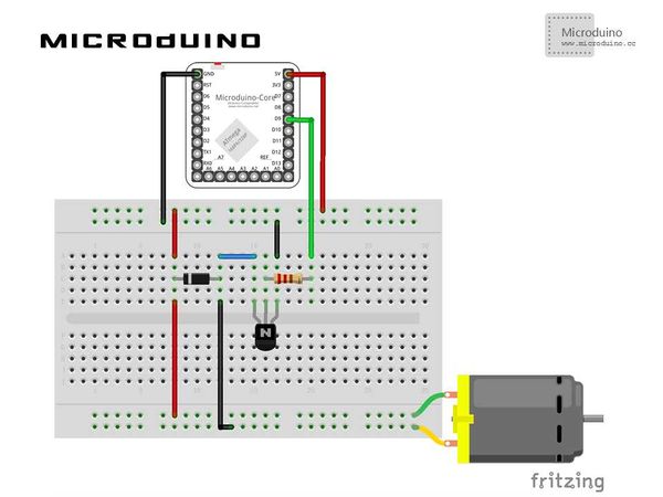
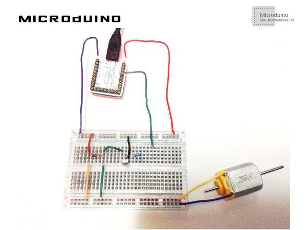
| − | Step | + | Step 1: Build hardware environment in accord with the schematic, just like this: |
[[File:processingDCMotorConnectionDiagram.jpg|600px|center|thumb]] | [[File:processingDCMotorConnectionDiagram.jpg|600px|center|thumb]] | ||
| − | Step | + | Step 2: Here the code we need: |
The code of the two ends (Processing and Microduino) | The code of the two ends (Processing and Microduino) | ||
| Line 90: | Line 90: | ||
} | } | ||
| − | Step | + | Step 3: Download the code and get it compiled successfully. . |
| − | Step | + | Step 4: Move your mouse around in "Processing" after the system goes well to see speed change of the motor. |
==Result== | ==Result== | ||
Latest revision as of 09:20, 13 September 2016
Contents[hide]ObjectiveThe course will show you how to use "Processing" to control the speed of the DC motor. Equipment
SchematicProgramRefer to MicroduinoDCMotorControl ProcessingDCMotorControl DebuggingStep 1: Build hardware environment in accord with the schematic, just like this:
The code of the two ends (Processing and Microduino) Microduino: //Send output value to the motor after getting the serial data if(Serial.available())//if serial is available
{
leitura=Serial.read();//read serial data
Serial.println(leitura);
vel=map(leitura,0,255,0,1023);//map
if(leitura>0)//run motor by leitura
{
analogWrite(motorPin,vel);
delay(1);
}
else//stop motor
{
analogWrite(motorPin,LOW);
}
}
Processing: //List all the serial ports and get data of the first serial port // List all the available serial ports in the output pane. // You will need to choose the port that the Wiring board is // connected to from this list. The first port in the list is // port #0 and the third port in the list is port #2. println(Serial.list()); // Open the port that the Wiring board is connected to (in this case #0) // Make sure to open the port at the same speed Wiring is using (9600bps) port = new Serial(this, Serial.list()[0], 9600); //Draw and update void draw()
{
background(0);
update(mouseX/10);
println(mouseX);
}
//Transmit the x-coordinate value of the mouse through the serial port and draw the current value on Processing void update(int x)
{
port.write(x);
stroke(255);
line(mouseX, 0, mouseX, 160);
text (mouseX, mouseX, 180);
}
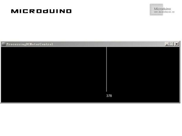
Step 3: Download the code and get it compiled successfully. . Step 4: Move your mouse around in "Processing" after the system goes well to see speed change of the motor. ResultA simple speed indicator will be displayed on the screen. The speed of the motor will change along with the change of your mouse on the x-coordinate.
Video |


