Difference between revisions of "The Use of Joystick Sensor"
From Microduino Wiki
(→Development) |
(→Preparation) |
||
| Line 40: | Line 40: | ||
===Preparation=== | ===Preparation=== | ||
*Setup 1:Connect Microduino-Joystick and the Hub 's A0 and A1 analog ports. | *Setup 1:Connect Microduino-Joystick and the Hub 's A0 and A1 analog ports. | ||
| − | [[file:mCookie- | + | [[file:mCookie-joystick.JPG|600px|center]] |
*Setup 2:Stack the CoreUSB, Hub and Light together and then connect them to the computer with a USB cable. | *Setup 2:Stack the CoreUSB, Hub and Light together and then connect them to the computer with a USB cable. | ||
[[file:mCookie-joystick.JPG|600px|center]] | [[file:mCookie-joystick.JPG|600px|center]] | ||
Revision as of 04:32, 9 November 2015
ContentsOutlineMicroduino-Joystick sensor is equipped with a two-way analog output interface. Its output values correspond to offsets on both the X-axis and Y-axis. It is small and beautiful. Specification
DevelopmentEquipment
Preparation
Experiment: Detect Analog Brightness Value
#define Pin_X A1
#define Pin_Y A0

void setup() {
  Serial.begin(9600);    //Serial initializing
  pinMode(Pin_X,INPUT);
  pinMode(Pin_Y,INPUT);
}

void loop() {
  int sensorValueX = analogRead(Pin_X);      //X-axis input
  int sensorValueY = analogRead(Pin_Y);      //Y-axis input
  Serial.print("ValueX:");
  Serial.print(sensorValueX);
  Serial.print(",");
  Serial.print("ValueY:");
  Serial.println(sensorValueY);
  delay(100);
}
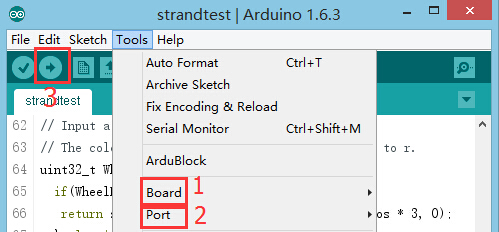
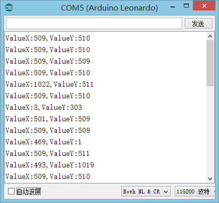
Program Debugging
Application
Video |

